Overview
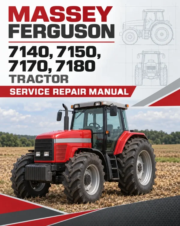
The Massey Ferguson 7140, 7150, 7170 and 7180 Tractor Workshop Service Repair Manual provides detailed technical information for maintaining, inspecting, troubleshooting and repairing these Massey Ferguson MF 7100 Series agricultural tractors. The workshop documentation covers SISU diesel engines, heavy-duty clutch assemblies, ZF T-600 transmissions, rear axle and differential components, independent power take-off systems, ZF four-wheel-drive front axles, hydraulic steering equipment, auxiliary hydraulic circuits, electronic lifting systems, electrical equipment and operator cab systems.
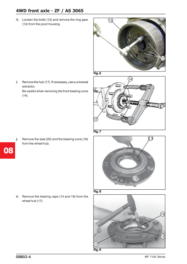
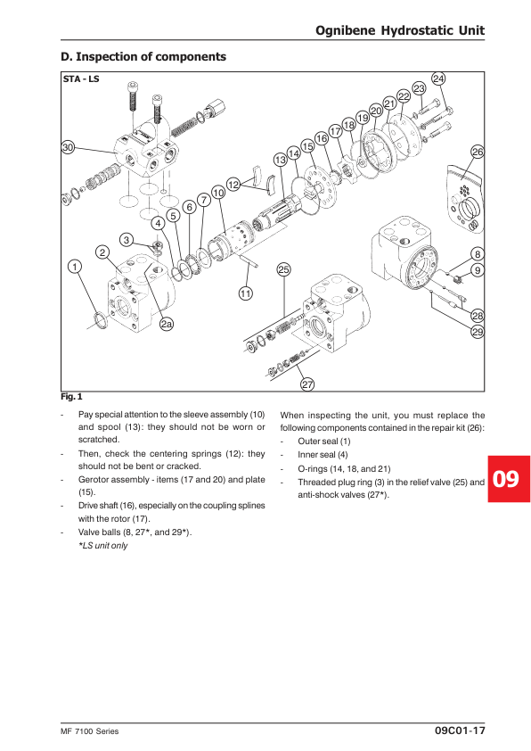
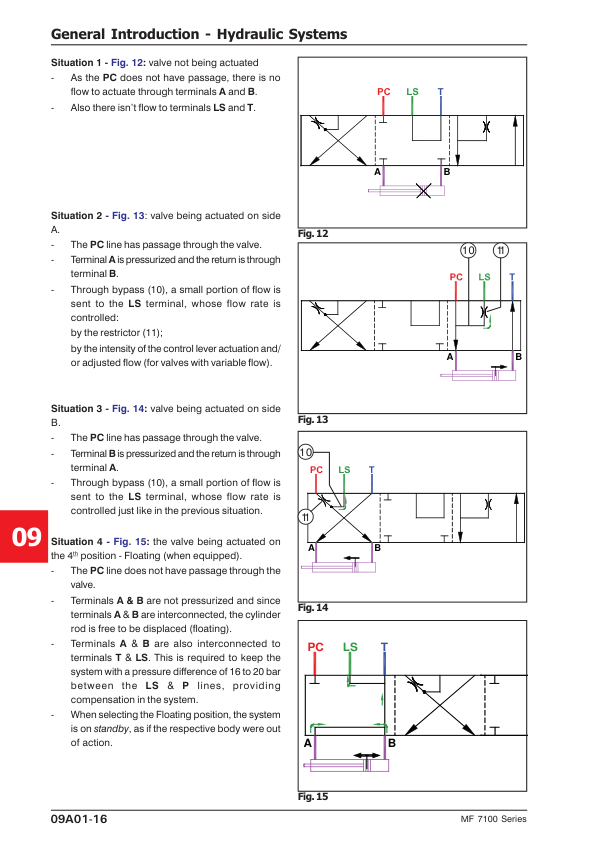
Technical coverage includes SISU engine cylinder head and crankshaft servicing, fuel injection pump adjustment, turbocharger inspection, clutch overhaul, transmission shaft repairs, rear differential and final drive adjustments, independent PTO clutch maintenance and ZF AS 3050/3065 front axle servicing. Additional chapters address Load Sensing hydraulics, hydraulic pump overhaul, Hydrotronic and Boschtronic electronic lift controls, Husco hydraulic equipment, Ognibene hydrostatic steering, pneumatic trailer brake components, hydraulic pressure testing and cab and air-conditioning references.
Important Information: The workshop documentation identifies model-specific transmission layouts, PTO speed arrangements, hydraulic circuits and auxiliary control systems. Separate hydraulic references are provided for the MF 7140 and the MF 7150, 7170 and 7180 tractors. The manual also covers different electronic lifting systems, including Hydrotronic, Boschtronic and Husco equipment. Confirm the tractor model and installed components before selecting the applicable repair, adjustment or diagnostic procedures.
Table of Contents
Massey Ferguson 7140, 7150, 7170, 7180 Manual
-
01. Introduction, Specifications and Workshop Safety
- MF 7100 Series Workshop Manual Introduction
- Using the Workshop Service Manual
- General Workshop Safety Instructions
- Correct Workshop Repair Techniques
- Recommended Bolt Tightening Torques
- Technical Measurement Units
- Measurement Conversion Tables
- Imperial and SI Unit Equivalents
- Workshop Locking and Sealing Products
- Tractor Paintwork Products
- AGCO Environmental Policy
- Battery Recycling Requirements
- MF 7100 Series Technical Specifications
- Diesel Engine General Specifications
- Engine Lubrication System Specifications
- Engine Cooling System Specifications
- Engine Air Filtration System
- Diesel Fuel System Specifications
- Electrical System Ratings
- Clutch Specifications
- 12×5-Speed Transmission Specifications
- Maximum Theoretical Road Speeds
- Rear Axle Specifications
- Four-Wheel-Drive Front Axle Specifications
- Brake System Specifications
- Hydraulic Lift Specifications
- Hydrostatic Steering Specifications
- Independent Auxiliary Hydraulic System
- Independent Power Take-Off Specifications
- Tractor Weight and Ballasting References
- General Tractor Dimensions
- Fluid Refilling Capacities
- Approved Lubricants and Additives
- Drawbar Specifications
- Cab and Air Conditioning Specifications
- Transmission and PTO Layout Diagrams
- MF 7140 Transmission Layout with 540 RPM IPTO
- MF 7140 Transmission Layout with 540/1000 RPM IPTO
- MF 7150 and MF 7170 Layout with 1000 RPM IPTO
- MF 7150 and MF 7170 Layout with 540/1000 RPM IPTO
- MF 7180 Transmission Layout with 1000 RPM IPTO
- MF 7180 Transmission Layout with 540/1000 RPM IPTO
-
02. Splitting the Tractor and Major Component Separation
- Tractor Splitting General Information
- Separating the Engine and Front Axle
- Engine and Front Axle Splitting Procedure
- Engine and Front Axle Reassembly
- Separating the Engine and Transmission Gearbox
- Engine and Gearbox Splitting Procedure
- Engine and Gearbox Reassembly
- Separating the Gearbox and Rear Axle
- Gearbox and Centre Housing Separation
- Gearbox and Rear Axle Reassembly
- Engine Hood and Sheet Metal Components
- Front Hood Component Identification
- Front Hood Sheet Metal Removal
- Operator Platform Removal
- Tractor Weight Fastening
- Cab Tractor Separation Procedures
- Cab Tractor Engine and Front Axle Separation
- Cab Tractor Engine and Gearbox Separation
- Cab Tractor Gearbox and Rear Axle Separation
- Rear Axle Trumpet Removal
- Operator Cab Removal
- Cab and Platform Fastening
- Air Conditioning Hoses During Cab Removal
- Cab Heating System Hot Water Hoses
-
03. SISU Diesel Engines and Associated Systems
- Diesel Engine Service Introduction
- Engine Cleaning Recommendations
- Diesel Fuel Quality Specifications
- Engine Lubricating Oil Quality
- Coolant and Antifreeze Requirements
- Inactive Engine Maintenance
- Diesel Engine Troubleshooting
- Turbocharger Troubleshooting
- Fuel Injection Nozzle Inspection
- Injector Nozzle Pressure Testing
- Fuel Injector Sealing Test
- Fuel Injector Atomisation Testing
- Engine Cylinder Compression Testing
- SISU Diesel Engine Identification
- Engine Serial Number Location
- Engine Model Designations and Types
- Engine Manufacturing Year Identification
- SISU Engine Basic Specifications
- Engine Construction and Main Features
- Preventive Engine Maintenance
- Access to Engine Service Points
- Engine Lubrication Maintenance
- Engine Air Supply System
- Diesel Fuel System Maintenance
- Engine Cooling System Maintenance
- Crankcase Breather Hose Cleaning
- Engine Drive Belt Tension Adjustment
- Engine Thermostat Servicing
- Engine Cooling Water Pump Rebuilding
- Coolant Quality and Cooling System Additives
- Engine Lubrication System
- Lubrication System Valve Rebuilding
- Engine Oil Pump Removal and Disassembly
- Oil Pump Servicing and Reassembly
- Piston Cooling Oil Injectors
- Diesel Engine Fuel Injection System
- Fuel Injection Nozzles
- Lucas/Delphi Fuel Injection Pump
- Fuel Injection Pump Timing
- Fuel Injection Angle and Timing Point
- Engine Valve Control System
- Engine Valve Clearance Adjustment
- Rocker Arm Assembly Rebuilding
- Valve Control Shaft and Gear Replacement
- Engine Timing Mechanism
- Timing Gear Cover Removal
- Idler Gear Rebuilding
- Timing Gear Adjustment
- Belt Tensioner Pulley and Bearing
- Engine Cylinder Head
- Cylinder Head Removal
- Engine Valve Removal
- Cylinder Head Inspection
- Valve Guide Replacement
- Valve Seat Reconditioning
- Valve Seat Ring Replacement
- Valve Machining and Adjustment
- Cylinder Head Adjustment
- Engine Cylinder Block
- Cylinder Liner Wear Measurement
- Cylinder Liner Removal and Installation
- Cylinder Block Inspection
- Valve Control Shaft Bearing Bushing Replacement
- Rear Plug Installation
- Engine Oil Dipstick Tube Installation
- Engine Pistons and Connecting Rods
- Piston and Connecting Rod Removal
- Connecting Rod Bearing Inspection and Replacement
- Connecting Rod Inspection
- Piston Ring Inspection and Replacement
- Piston Inspection
- Engine Crankshaft
- Crankshaft Removal
- Crankshaft Inspection
- Crankshaft Reassembly
- Crankshaft Hub Repair
- Crankshaft Pulley and Damper Replacement
- Crankshaft Vibration Damper Inspection
- Flywheel Housing and Rear Crankshaft Oil Seal
- Crankshaft Rear Oil Seal Replacement
- Engine Intake and Exhaust System
- Turbocharger Inspection
- Turbocharger Adjustment
- SISU Engine Workshop Specifications
- Engine Component Tightening Torques
- Special Engine Service Tools
- Engine Air Filtration System
- Fuel Tank and Throttle Control
- Throttle Control Component Identification
- Throttle Control Operation and Adjustment
- Radiator Servicing
- Water Pump Bearing Lubrication
- Cooling System Heat Exchanger Servicing
- Engine Exhaust System
- Cold Starting System Testing
- Tier II Diesel Engine Differences
- Bosch VE-Type Fuel Injection Pump
- Bosch Injection Pump Specifications
- Bosch Injection Pump Troubleshooting
- Fuel Injection Pump Removal and Timing Adjustment
- Tier II Injector Nozzle Adjustment
-
04. Heavy-Duty Clutch Assemblies
- Clutch Types Used on MF 7100 Series Tractors
- Heavy-Duty Single-Stage Diaphragm Spring Clutch
- Double-Disc Clutch Assembly
- General Clutch Service Recommendations
- Common Causes of Clutch Overheating
- Clutch Removal and Installation Precautions
- Clutch Troubleshooting
- Clutch Failure to Release
- Clutch Slipping
- Clutch Judder and Vibration
- Clutch Noise Diagnosis
- Clutch Application Specifications
- MF 7100 Series Clutch Technical Specifications
- Heavy-Duty Single Clutch Disassembly
- Single Clutch Component Inspection
- Single Clutch Reinstallation
- Double-Disc Clutch Component Identification
- Double-Disc Clutch Removal and Disassembly
- Double-Disc Clutch Component Inspection
- Clutch Component Machining
- Double-Disc Clutch Reassembly
- Clutch and Flywheel Final Adjustments
- Engine Flywheel Reinstallation
- Flywheel Alignment
- Flywheel Machining
- Clutch Pedal Free-Travel Adjustment
- Clutch Release Mechanism
- Clutch Release Mechanism Removal and Disassembly
- Clutch Release Component Inspection
- Clutch Release Mechanism Reassembly
-
05. ZF T-600 Transmission Gearbox
- ZF T-600 Transmission Introduction
- ZF Transmission Component Identification
- ZF T-600 Technical Specifications
- Transmission Adjustment Values
- ZF T-600 Gearbox Disassembly
- Transmission Housing and Peripheral Components
- Transmission Oil Pump Gearbox
- Front Wheel Drive Drop Gearbox
- High, Low and Reverse Selector Assembly
- Transmission Mainshaft and Intermediate Shaft
- Power Take-Off Drive Shaft
- Gearbox Front Cover
- ZF T-600 Gearbox Reassembly
- Transmission Mainshaft Assembly and Adjustment
- Intermediate Shaft Assembly and Adjustment
- Transmission Reduction Gear Assembly
- PTO Assembly Shaft
- PTO Drive Shaft Assembly
- Front Wheel Drive Engagement Gears
- Reverse Gear Assembly
- Transmission Oil Pump Drive Assembly
- Front Wheel Drive Drop Gearbox Reassembly
- PTO Cover Assembly
- Intermediate and Main Shaft Reinstallation
- Transmission Housing Reassembly
- Transmission External Controls
- Gearbox Control Cables and Levers
- Gear Selector Lever Positions
- Transmission Engagement Lever Identification
- Transmission Control Service and Maintenance
- Gearbox Control Cable Adjustment
-
06. Rear Axle, Differential and Brakes
- Rear Axle General Description
- Rear Axle Technical Specifications
- Rear Brake and Drive Specifications
- Rear Differential Specifications
- Rear Drive Pinion Specifications
- Differential and Pinion Gear Ratios
- Rear Axle Trumpet Specifications
- Rear Final Drive Assemblies
- 6.0:1 and 8.47:1 Final Drive Component Identification
- Rear Final Drive Removal
- Rear Final Drive Disassembly
- Final Drive Component Inspection and Replacement
- Rear Final Drive Reassembly
- Final Drive Bearing Preload Adjustment
- Rear Hydraulic Brake System
- Hydraulic Brake Circuit
- Brake Hydraulic Circuit Air Bleeding
- Brake Master Cylinder Pushrod Clearance Adjustment
- Brake Pedal Free-Travel Inspection and Adjustment
- Brake Master Cylinder Maintenance
- Brake Servo Cylinder Maintenance
- Brake Equalising Valve Servicing
- Parking Brake Operating Principles
- Parking Brake Adjustment
- Rear Brake Disc Assemblies
- Brake Disc Component Identification
- Brake Disc Disassembly
- Brake Component Inspection
- Brake Actuating Rod Protective Cap Replacement
- Brake Disc and Plate Reassembly
- Rear Axle Trumpet Removal and Disassembly
- Rear Axle Trumpet Reinstallation
- Differential Lock System
- Differential Lock Component Identification
- Differential Lock Disassembly
- Differential Lock Component Inspection
- Differential Lock Reassembly
- Differential Lock Actuation Adjustment
- Differential Carrier and Ring Gear
- Differential Carrier Component Identification
- Differential Assembly Removal and Disassembly
- Differential Component Inspection
- Ring Gear Distortion Inspection
- Differential Reassembly and Final Adjustments
- Rear Drive Pinion Assembly
- Drive Pinion Component Identification
- Pinion Removal and Disassembly
- Drive Pinion Component Inspection
- Pinion Reassembly
- Pinion Bearing Preload Adjustment
- Pinion Position Adjustment – MF 7150, 7170 and 7180
- Ring Gear and Pinion Reinstallation
- Differential Bearing Preload Adjustment
- Ring Gear and Pinion Backlash Adjustment
- Ring Gear and Pinion Tooth Contact Inspection
-
07. Independent Power Take-Off (IPTO)
- Power Take-Off General Description
- PTO Component Identification
- Independent PTO Clutch
- PTO Safety Brake
- Engine Speed and PTO Output Shaft Speed
- Dual-Speed PTO – 540 and 1000 RPM
- Independent PTO Removal
- Independent PTO Reinstallation
- Independent PTO Control System
- IPTO Hydraulic Clutch Assembly
- Hydraulic PTO Clutch Component Identification
- PTO Clutch Disassembly
- PTO Clutch Component Inspection
- Hydraulic PTO Clutch Reassembly
- IPTO Hydraulic Control Cover
- Hydraulic Oil Flow with PTO Disengaged and Brake Applied
- Hydraulic Oil Flow with PTO Engaged
- IPTO Control Cover Component Identification
- IPTO Control Cover Removal and Disassembly
- IPTO Control Cover Component Inspection
- IPTO Control Cover Reassembly
- IPTO Pressure-Maintaining Valve
- 540/1000 RPM PTO Configuration
- PTO Output Shaft Replacement
- IPTO Control Panel Programming
- Power Take-Off Output Shaft
- PTO Output Shaft Component Identification
- PTO Shaft Removal and Disassembly
- PTO Shaft Component Inspection
- PTO Output Shaft Reassembly and Installation
-
08. ZF Four-Wheel-Drive Front Axles – AS 3050 and AS 3065
- ZF Four-Wheel-Drive Front Axle Specifications
- ZF AS Series Front Axle Models and Versions
- ZF AS 3050 Front Axle Adjustment Specifications
- ZF AS 3065 Front Axle Adjustment Specifications
- ZF AS 3050 Front Axle
- AS 3050 Final Drive Components
- AS 3050 Final Drive Disassembly and Removal
- AS 3050 Final Drive Component Inspection
- AS 3050 Final Drive Reassembly and Adjustment
- AS 3050 Final Drive Pivot Assembly
- Final Drive Pivot Disassembly and Inspection
- Final Drive Pivot Reassembly and Adjustment
- Front Axle Universal Joint Spiders and Shafts
- Axle Shaft Removal and Installation
- Universal Joint Spider Inspection
- Front Axle Trumpet Bushings and Retainers
- Pivot Bushing Inspection and Reassembly
- AS 3050 Front Differential and Drive Pinion
- Front Axle Removal
- Front Differential Removal and Disassembly
- Front Differential Component Inspection
- Drive Pinion Disassembly and Reassembly
- Drive Pinion Position Adjustment
- Pinion Bearing Preload Adjustment
- Ring Gear and Pinion Backlash Adjustment
- Ring Gear and Pinion Contact Pattern Inspection
- Front Differential Final Reassembly
- AS 3050 Central Front Drive Gearbox
- Secondary Drive Box Disassembly
- Secondary Drive Box Inspection and Reassembly
- Front Axle Support Bearings
- Front Axle Longitudinal Play Adjustment
- Axle Support Bracket and Bearing Servicing
- Front Hydraulic Steering Cylinder
- Steering Cylinder, Rod and Pivot Removal
- Steering Cylinder Component Inspection
- Steering Cylinder Reassembly and Adjustment
- ZF AS 3065 Front Axle
- AS 3065 Final Drive Component Identification
- AS 3065 Final Drive Disassembly and Removal
- AS 3065 Final Drive Component Inspection
- AS 3065 Final Drive Reassembly
- AS 3065 Final Drive Pivoting Assembly
- Pivot Assembly Removal and Disassembly
- Pivot Assembly Reassembly and Adjustment
- Pivot Bearing Preload Adjustment
- AS 3065 Axle Shafts and Universal Joint Spiders
- Spider Removal, Inspection and Reassembly
- AS 3065 Trumpet Bushings and Retainers
- AS 3065 Front Differential and Pinion
- Front Differential Removal and Disassembly
- Differential and Pinion Inspection
- Drive Pinion Positioning and Preload Adjustment
- Crownwheel and Pinion Backlash Adjustment
- Ring Gear and Pinion Tooth Contact Inspection
- Front Differential Reassembly
- AS 3065 Secondary Drive Gearbox
- Secondary Drive Gearbox Disassembly and Reassembly
- Front Axle Support Bearing Adjustment
- Hydraulic Steering Cylinder Servicing
- Front Wheel Drive Engagement System
- Four-Wheel-Drive Engagement Box Servicing
- Engagement Box Disassembly and Reassembly
- Four-Wheel-Drive Electrovalve Coil
-
09. Auxiliary Hydraulics, Hydrostatic Steering and Lift Systems
- Hydraulic System General Introduction
- Auxiliary Hydraulic System Variations
- Hydraulic System Component Identification
- Hydraulic Circuit Diagrams
- Hydraulic System Operating Principles
- Hydraulic Filtration Monitoring
- MF 7150, 7170 and 7180 Auxiliary Hydraulic Controls
- MF 7150–7180 Three-Point Linkage Hydraulics
- MF 7140 Auxiliary Hydraulic Control System
- MF 7140 Three-Point Linkage Hydraulics
- MF 7140 Hydraulic Circuit with IPTO and Lift
- MF 7150, 7170 and 7180 Hydraulic Circuit with IPTO and Lift
- Hydraulic Pump Assemblies
- Hydraulic Pump Component Identification
- Hydraulic Pump Removal and Disassembly
- Hydraulic Pump Inspection and Troubleshooting
- Hydraulic Pump Reassembly
- Hydraulic Load Sensing System
- Load Sensing Valve Operating Principles
- Load Sensing Valve Component Identification
- Load Sensing Valve Removal and Disassembly
- FR1 and FR2 Hydraulic Restrictor Valves
- CV1 Hydraulic Retaining Valve
- EP1 and EP2 Directional Valves
- RV1 Hydraulic Relief Valve
- PD1 Hydraulic Directional Valve
- Hydraulic Oil Filtration System
- Hydraulic Suction Filter Maintenance
- Hydraulic Pressure Filter Maintenance
- Hydraulic Return Filter Maintenance
- Hydraulic Return Gallery Pressure-Maintaining Valve
- Hydraulic Heat Exchanger Bypass Valve
- Gearbox Lubrication Pressure-Maintaining Valve
- Hydraulic Heat Exchanger Servicing
- Hydraulic Heat Exchanger Sealing Test
- Pneumatic Trailer Brake System
- Pneumatic Trailer Brake Component Identification
- Trailer Pneumatic Brake Assembly
- Pneumatic Brake Circuit Diagram
- Hydraulic Lift Cover Assembly
- Hydraulic Lift Cover Disassembly
- Hydraulic Lift Cover Reassembly and Installation
- Hydraulic Lift Cylinders
- Inner Hydraulic Lift Cylinder
- Inner Lift Cylinder Removal and Disassembly
- Inner Lift Cylinder Inspection and Reassembly
- Outer Lift Cylinder Mounted on Hydraulic Cover
- Outer Hydraulic Cylinder Disassembly and Inspection
- Outer Hydraulic Cylinder Reassembly
- Rear-Mounted Outer Lift Cylinders – 4500 kgf System
- Rear-Mounted Outer Lift Cylinders – 5500 kgf System
- Hydraulic Lift Control Valve
- Hydraulic Lift Control Valve Circuit Operation
- Hydraulic Lift Control Valve Removal and Disassembly
- Hydraulic Lift Raising Solenoid
- Hydraulic Lift Lowering Solenoid
- Hydraulic Lift Control Valve Inspection and Reassembly
- Hydrotronic Electronic Hydraulic Lift System
- Hydrotronic Component Identification
- Hydrotronic Hydraulic Circuit
- Hydrotronic Electrical Wiring Diagrams
- Hydrotronic Technical Specifications
- Hydrotronic Control Panel Components
- Hydrotronic Electronic System Reset
- Hydrotronic Position Sensor Installation and Adjustment
- Hydrotronic Position Sensor Adjustment Testing
- Hydrotronic Draft Sensor Installation and Adjustment
- Hydrotronic Control Panel Buttons and Switches
- Hydrotronic Electronic Control Unit (CPU)
- Hydrotronic Wiring Harness and Connectors
- Hydrotronic Position Sensor Testing
- Hydrotronic Draft Sensor Testing
- Hydrotronic Fault Diagnosis
- Hydrotronic Diagnostic Trouble Code Tables
- Boschtronic Electronic Hydraulic Lift System
- Boschtronic Component Identification
- Boschtronic Hydraulic Circuit
- Boschtronic Electrical Wiring Diagrams
- Boschtronic Technical Specifications
- Boschtronic Control Panel Components
- Boschtronic Electronic System Reset
- Boschtronic Position Sensor Installation and Adjustment
- Boschtronic Draft Sensor Installation and Adjustment
- Boschtronic Control Panel Electronic Circuit
- Boschtronic Electronic Control Unit (CPU)
- Boschtronic Wiring Harness and Connectors
- Boschtronic Position Sensor Testing
- Boschtronic Draft Sensor Testing
- Boschtronic Fault Diagnosis
- Boschtronic Diagnostic Trouble Code Tables
- Husco Hydraulic Lift System
- Husco Hydraulic Lifting Control Valve
- Husco Hydraulic Control Valve Circuit Operation
- Husco Lifting Control Valve Removal and Installation
- Ognibene Hydrostatic Steering Unit
- Ognibene Steering Unit Operating Principles
- Ognibene Steering Circuit with Engine Running
- Ognibene Steering Operation with Stationary Engine
- Ognibene STA-LS Hydrostatic Steering Unit
- Ognibene Steering Unit Hydraulic Circuit
- Ognibene Steering Unit Component Identification
- Ognibene Steering Unit Disassembly
- Ognibene Steering Unit Component Inspection
- Ognibene Steering Unit Reassembly
- Ognibene Hydraulic Relief Valve
- Ognibene Anti-Shock Valves
- Ognibene Load Sensing Priority Valve
- Priority Valve Hydraulic Connections
- Priority Valve Maintenance
- Remote Auxiliary Hydraulic Controls
- Remote Hydraulic Control Valve Component Identification
- Remote Hydraulic Valve Types and Detents
- Remote Hydraulic Control Removal and Disassembly
- Remote Hydraulic Control Valve Reassembly
- MF 7140 Remote Hydraulic Control Inlet Body
- Remote Hydraulic Control Cables
- General Hydraulic System Testing
- Hydraulic System Pressure Specifications
- MF 7140 Hydraulic Pressure Table
- MF 7150–7180 Hydraulic Pressure Table
- Hydrostatic Steering Pressure Testing – P1
- Load Sensing Steering Anti-Shock Valve Testing
- Hydraulic Lift and Remote Control Testing – P2
- PTO and Four-Wheel-Drive Hydraulic Testing – P3
- Husco Remote Hydraulic Control and Three-Point Lift
- Husco Valve Body Neutral Position
- Husco Valve Body Extension and Retraction
- Husco Floating Valve Body
- Husco High-Flow Valve Operations
- MF 7180 Hydraulic Input and Output Circuit
- MF 7140 Hydraulic Input and Output Circuit
- MF 7180 Load Sensing Hydraulic Circuit
- MF 7140 Load Sensing Hydraulic Circuit
- Husco Remote Control Valve Removal and Disassembly
- Husco Control Valve Disassembly and Reassembly
- Husco Valve Body and Spool Cleaning
- Husco Kick-Out Pressure Calibration
- Husco Remote Control Working Pressures
- Husco Hydraulic Valve Fault Diagnosis
- Husco Control Valve Tightening Torque Chart
-
10. Electrical System
-
11. Electronics Systems – Reserved Section
-
12. Cab and Air Conditioning Systems
Identifying PTO, Hydraulic Lift and Transmission Configurations
The Massey Ferguson 7140, 7150, 7170 and 7180 workshop documentation includes model-specific drivetrain and power take-off layouts. The introduction identifies separate configurations for the MF 7140 with 540 RPM or dual 540/1000 RPM independent PTO, while the MF 7150, MF 7170 and MF 7180 have their own documented IPTO layouts. The PTO service section also covers hydraulic clutch components, control valves, output shaft replacement and control panel programming.
Hydraulic equipment is another important distinction within the MF 7100 Series. The manual provides separate auxiliary hydraulic and three-point linkage circuit references for the MF 7140 and MF 7150–7180 models. These include Load Sensing circuits, hydraulic pumps, filtration systems, control valves and model-specific hydraulic pressure testing information.
Electronic hydraulic lifting systems are covered under Hydrotronic, Boschtronic and Husco references. The Hydrotronic and Boschtronic sections contain position and draft sensor adjustments, control panel and wiring references, diagnostic testing and fault code information. Husco documentation includes hydraulic valve operation, remote control servicing, pressure calibration and fault diagnosis. Identify the installed hydraulic lift control system before selecting the corresponding repair or diagnostic procedures.
The transmission section covers the ZF T-600 gearbox, including internal shaft assemblies, selector components, front wheel-drive gearing and external cable adjustment. Front axle servicing is separately organised for ZF AS 3050 and AS 3065 assemblies, with individual differential, final drive, steering cylinder and bearing adjustment procedures.






















Reviews
There are no reviews yet.