Overview
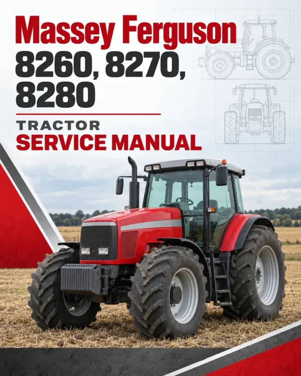
The Massey Ferguson 8260, 8270 and 8280 Tractor Workshop Service Repair Manual provides detailed technical information for maintaining, troubleshooting, servicing and repairing these Massey Ferguson agricultural tractors. The documentation covers tractor specifications, major assembly separation, engine-related components, clutch systems, Dynashift and Powershift transmissions, rear axles, differential assemblies, braking systems, power take-off equipment, front axles, hydraulic circuits, electrical systems and electronic controls.
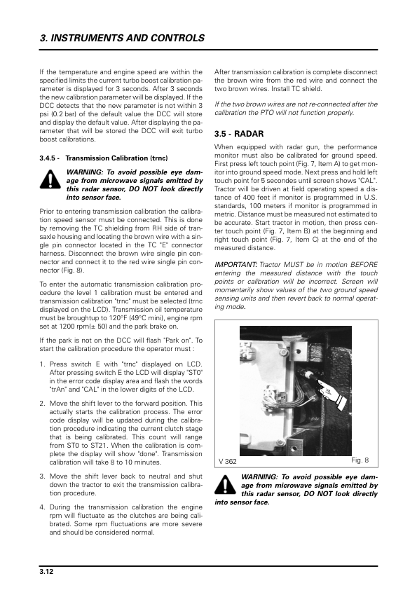
Workshop coverage includes Power Shuttle clutch repairs, Full Powershift transmission servicing, gearbox shaft and bearing adjustments, rear axle final drives, differential lock mechanisms, PTO shaft and clutch maintenance, Dana, ZF and Carraro front axle components, and Load Sensing hydraulic systems. Additional technical references include 110 and 150 L/min hydraulic circuit testing, Autotronic 2 and Autotronic 3 controls, Datatronic functions, electronic linkage diagnostics, Wintest programming procedures, wiring diagrams, calibration instructions and specialised workshop service tools.
Important Information: The workshop manual contains procedures for different tractor configurations, including Dynashift and Full Powershift transmissions, multiple front axle designs, optional suspended axle systems and different hydraulic equipment. Not every component or procedure applies to all MF 8260, 8270 and 8280 tractors. Verify the model, serial number and installed equipment before carrying out repairs.
Table of Contents
Massey Ferguson 8260, 8270, 8280 Tractor Workshop Service Manual
-
01. Introduction and Specifications
- 1A01 – Introduction
- Reading and Using the Workshop Manual
- General Tractor Specifications
- Safety Instructions
- Practical Workshop Advice
- Instructions for Putting the Tractor into Service
- Conversion Tables
- Locking Compounds and Sealants
- Tightening Torques
-
02. Splitting the Tractor
- 2A01 – Splitting Between Front Frame and Engine
- Front Frame Separation and Reassembly
- Carraro Front Axle Configuration
- 2B01 – Splitting Between Engine and Gearbox
- Engine and Gearbox Separation Procedures
- 2C01 – Splitting Between Gearbox and Intermediate Housing
- Heavy Duty Gearbox Separation
- 2D01 – Splitting Between Intermediate Housing and Centre Housing
- 2E01 – Separating PTO Housing and Centre Housing
- 2F01 – Chassis Reinforcements
- Heavy Duty Gearbox Chassis Reinforcement Adjustment
- 2G01 – Rear Wheels and Hubs
- Rear Wheel Assemblies and Tightening Torques
- Rear Wheel Track Adjustment
- Wheel Stud Replacement
-
03. Engine
- 3A01 – Engine General Information
- Engine Main Characteristics
- Viscostatic Cooling Fan
- 3B01 – Flywheel and Dampers
- Engine Damper Removal and Refitting
- Flywheel and Bearing Removal and Refitting
- Starter Ring Gear Replacement
- Flywheel Service Tools
- 3C01 – Engine Spacer
- Engine Spacer Removal and Refitting
- 3C02 – Power Shuttle Engine Spacer
- Power Shuttle Spacer Removal and Refitting
- Engine Spacer Service Tools
-
04. Clutch
- 4A01 – Pressure-Loaded Clutch
- Clutch Construction and Components
- Closing Plate Removal and Refitting
- Clutch Lip Seal and O-Ring Replacement
- Clutch Removal and Refitting
- Pressure-Loaded Clutch Adjustment
- Clutch Disassembly and Reassembly
- Clutch Control Valve Removal and Refitting
- Clutch Service Tools
-
05. Gearbox and Transmission Systems
- 5A01 – Gearbox General Information and Operation
- Gearbox Operating Principles and Specifications
- 5A02 – Gearbox General Information – Alternative Configuration
- Transmission Tightening Torques
- 5B01 – Input Unit with Mechanical Reverse Shuttle
- Mechanical Reverse Shuttle Input Unit Removal and Refitting
- 5B02 – Input Unit with Power Shuttle
- Power Shuttle Input Unit Removal and Refitting
- Progressive Sensor Adjustment
- 5B03 – Dynashift Transmission
- Dynashift Theory of Operation
- Front Clutch Housing and Brake Disassembly
- Planetary Carrier Removal and Separation
- Rear Clutch and Brake Servicing
- Planetary Carrier Assembly and Shimming
- Dynashift Input Unit Assembly
- 5B04 – Dynashift Transmission – Alternative Configuration
- Front Clutch Casing and Brake Removal
- Rear Clutch and Brake Reassembly
- Planet Carrier Shimming
- 5B05 – Mechanical Reverse Shuttle
- Mechanical Reverse Shuttle Operation
- 5B06 – Power Shuttle
- Power Shuttle Front Clutch Removal and Refitting
- Front Clutch Disassembly and Reassembly
- Power Shuttle Front Clutch Shimming
- Rear Clutch Disassembly and Reassembly
- Driving Pinion Disassembly and Reassembly
- Power Shuttle Shaft Shimming
- 5C01 – Selector Cover
- Selector Cover Removal and Refitting
- Hare/Tortoise Range Piston Seal Replacement
- Selector Mechanism Disassembly and Reassembly
- Gear Linkage and Reverse Shuttle Cable Adjustment
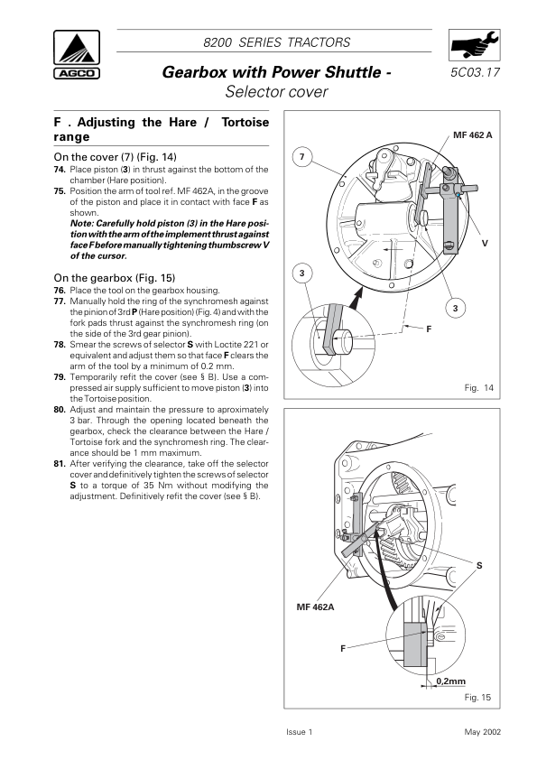
- Hare/Tortoise Range Adjustment
- 5C02 – Selector Cover – Alternative Configuration
- Gear Selector and Range Control Servicing
- 5C03 – Selector Cover with Optimised Hare/Tortoise Function
- Optimised Range Control Components
- Selector Mechanism and Piston Seal Servicing
- 5D01 – Selector Rails
- Selector Rail Removal and Reassembly
- Gearbox Selector Fork Adjustment
- Input Unit Selector Fork Adjustment
- 5D02 – Selector Rails – Alternative Configuration
- 5E01 – Output Shaft
- Output Shaft Removal and Refitting
- Output Shaft Shimming
- 5F01 – Mainshaft
- Mainshaft Disassembly and Reassembly
- Input Pinion and Mainshaft Shimming
- 5F02 – Mainshaft – Alternative Configuration
- 5G01 – Layshaft
- Layshaft Removal and Disassembly
- Layshaft Reassembly and Refitting
- Pinion and Bearing Shimming
- 5H01 – Power Transmission – General Information
- Power Transmission Construction and Characteristics
- Transmission Component Diagrams
- Vibration Damper and Coupling Shafts
- 5I01 – Transmission Hydraulic Circuit
- Transmission Hydraulic Circuit Specifications
- Transmission Oil Filter
- Thermostatic Valve
- Pressure Regulating Valve
- Proportional Solenoid Valve
- Transmission Hydraulic Pump and Pressure Circuit
- Hydraulic Pump Disassembly and Reassembly
- Transmission Clutch and Lubrication Circuits
- 5J01 – Transmission Repair
- Gearbox Disassembly and Reassembly
- Front Housing Removal
- Clutch and Transmission Shaft Removal
- Input Shaft Seal Replacement
- Gearbox Housing Inspection and Repair
- Speed Clutch Train Overhaul
- Range Clutch Shaft Repair
- 5K01 – Creeper Unit
- Creeper Gear Operating Principles
- Creeper Unit Removal and Installation
- Creeper Gear Selector Adjustment
- Epicyclic Reduction Gear Disassembly and Reassembly
-
06. Rear Axle, Differential and Braking System
- 6A01 – Rear Axle Description
- Rear Axle Main Components
- 6B01 – Standard Trumpet Housings
- Trumpet Housing Removal and Refitting
- Brake Plate and Crown Wheel Assembly
- Planetary Carrier Disassembly and Reassembly
- Axle Shaft Bearing Replacement and Shimming
- Wheel Stud Replacement
- 6B02 – Trumpet Housings with Sealed Compartment
- Sealed Compartment and Crown Wheel Servicing
- Compartment Seal Replacement
- Planetary Carrier and Axle Bearing Servicing
- 6B03 – Trumpet Housings with Composite Drive Unit
- Composite Drive Unit Removal and Refitting
- Spacer and Crown Wheel Assembly
- Spacer Seal and Cassette Seal Replacement
- Planetary Gear Shimming
- 6B04 – Trumpet Housings with Double Reduction
- Double Reduction Final Drive Servicing
- Epicyclic Reduction Gear Components
- Planetary Gear Disassembly and Reassembly
- 6C01 – Handbrake Unit and Control Linkage
- Handbrake Disassembly and Reassembly
- Handbrake Control Adjustment
- Handbrake Lever and Cable Replacement
- 6D01 – Differential with Standard Bevel Gear and Hydromechanical Lock
- Differential Lock Carrier Removal and Refitting
- Differential Unit and Crown Wheel Servicing
- Planetary and Sun Gear Disassembly
- Differential Backlash Adjustment
- Differential Unit Shimming
- Drive Pinion Removal and Refitting
- 6D02 – Differential with Standard Bevel Gear and Multidisc Lock
- Multidisc Differential Lock Servicing
- Crown Wheel and Pinion Adjustment
- Differential Bearing and Pinion Shimming
- 6D03 – Differential with Hypoid Bevel Gear and Multidisc Lock
- Hypoid Differential Overhaul
- Multidisc Lock Adjustment
- Drive Pinion Position and Shimming
- 6E01 – Brake Pistons and Seals
- Brake Piston Disassembly and Reassembly
- 6F01 – Park Lock
- Park Lock Release Procedure
- Park Lock Sleeve Removal and Refitting
- Park Lock Control Disassembly and Reassembly
- 6G01 – Lift Cylinder Supports
- Lift Cylinder Shaft and Support Servicing
- 6H01 – Creeper Gear Mechanism
- Creeper Unit and Selector Servicing
- Epicyclic Reduction Gear Overhaul
- 6I01 – Brackets and Automatic Hook
- Automatic Hook and Drawbar Components
- Dromone Retractable Hook Operating Principles
- 6J01 – Rear Hitch Mechanism
- Rear Hitch Components
- Rear Lift Cylinder Disassembly and Reassembly
-
07. Power Take-Off (PTO)
- 7A01 – Power Take-Off Description
- Power Take-Off Main Components
- 7B01 – Driving Pinions, Bearings and Layshaft
- PTO Driving Pinion Removal and Refitting
- PTO Bearing and Layshaft Servicing
- PTO Shaft Shimming
- 7C01 – Removable PTO Shaft
- 540/1000 RPM PTO Pinion Servicing
- 750/1000 RPM PTO Pinion Servicing
- Front Bearing Block Disassembly and Reassembly
- PTO Shaft Oil Seal Replacement
- Removable PTO Shaft Adjustment
- 7D01 – Shiftable PTO Shaft
- Shiftable PTO Gear and Bearing Servicing
- Rear Bearing Block and Oil Seal Replacement
- Shiftable PTO Shaft Shimming
- Long Shaft PTO Version
- PTO Control Adjustment
- 7E01 – 1000 RPM Power Take-Off Shaft
- 1000 RPM PTO Pinion and Bearing Servicing
- Rear Bearing Block and Shaft Oil Seal
- 1000 RPM PTO Shaft Adjustment
- 7F01 – PTO Clutch and Brake
- PTO Clutch Removal and Refitting
- PTO Clutch Disassembly and Reassembly
- PTO Clutch Service Tools
-
08. Front Axle, Four-Wheel Drive and Steering
- 8A01 – Carraro Front Axle – General Information
- Carraro Front Axle Construction
- Carraro Front Axle Safety Instructions
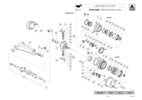
- 8B01 – Dana Final Drive Units
- Dana Planetary Carrier and Sun Gear Servicing
- Dana Front Wheel Hub Disassembly and Reassembly
- Swivel Housing Adjustment and Shimming
- Universal Drive Shaft Removal and Refitting
- 8B02 – ZF Final Drive Units
- ZF Planetary Carrier and Wheel Hub Servicing
- Wheel Hub Bearing and Oil Seal Replacement
- Wheel Hub Rotational Torque Adjustment
- Swivel Housing and Drive Shaft Servicing
- 8B03 – Carraro Final Drive Units
- Carraro Steering Cylinder Disassembly
- Epicyclic Reduction Gear Overhaul
- Wheel Hub and Axle Beam Servicing
- Front Wheel Toe-In Adjustment
- Steering Angle Adjustment
- 8C01 – Dana Differential
- Dana Front Differential Disassembly and Reassembly
- Differential Lock Removal and Refitting
- Crown Wheel and Drive Pinion Servicing
- 8C02 – ZF Differential
- ZF Differential Housing and Crown Wheel Repair
- Differential Backlash Adjustment
- Drive Pinion Bearing Shimming
- 8C03 – Carraro Differential
- Carraro Differential Support Group Servicing
- Drive Pinion and Differential Gear Assembly
- 8D01 – Two-Wheel-Drive Front Axle
- Steering Arm Ball Joint Removal and Refitting
- Front Hub and Axle Spindle Servicing
- Front Axle Removal and Refitting
- Wheel Alignment and Track Adjustment
- 8E01 – Steering Column
- Steering Column Disassembly and Reassembly
- Steering Lever, Shaft and Bearing Servicing
- 8F01 – Dana Front Axle Bearings and Transmission Shafts
- 8F02 – ZF Front Axle Bearings and Transmission Shafts
- 8F03 – Carraro Front Axle Bearings and Transmission Shafts
- Four-Wheel-Drive Transmission Shaft Servicing
- Universal Joint and Bearing Replacement
- 8G01 – Four-Wheel-Drive Clutch
- 4WD Clutch Removal and Refitting
- 4WD Clutch Disassembly and Shimming
- 8G02 – Carraro Suspension
- Carraro Suspension Arm Removal and Installation
- 8I01 – Carraro Troubleshooting
- Front Axle Fault Diagnosis
-
09. Hydraulic Systems
- 9A01 – 110 L/min Hydraulic Circuit
- 110 L/min Load Sensing Circuit Description
- Centre Housing Lubrication Circuit
- Hydraulic Circuit Component Locations
- 9A02 – 150 L/min Hydraulic Circuit
- 150 L/min Load Sensing Circuit Description
- Full Powershift Hydraulic Circuit Diagrams
- 9B01 – Priority Blocks with Trailer Braking
- Trailer Brake Priority Valve Operation
- 9C01 – Priority Blocks Without Trailer Braking
- Priority Valve Port Identification
- 9D01 – Auxiliary Spool Valves
- Auxiliary Spool Valve Types and Operation
- Auxiliary Valve Removal and Refitting
- 9D02 – Bosch Auxiliary Spool Valves
- Bosch Spool Valve Disassembly and Reassembly
- Hydraulic Control Cable Adjustment
- 9D03 – Electrohydraulic Spool Valves
- Electrohydraulic Valve Assembly
- Electrohydraulic Control Lever Adjustment
- 9E01 – Lift Control Spool Valve
- Lift Valve Removal and Refitting
- Lift Valve Neutral, Raise and Lower Positions
- 9F01 – Hydrostatic Steering
- Load Sensing Steering Operating Principles
- Orbitrol Steering Unit Disassembly and Reassembly
- Dana and Carraro Steering Ram Servicing
- 9F02 – Hydrostatic Steering for APL5052 Four-Wheel-Drive Axles
- APL5052 Steering Control and Ram Servicing
- 9G01 – Right-Hand Cover – 110 L/min Load Sensing
- Variable-Displacement Hydraulic Pump
- Hydraulic Pump Removal and Refitting
- Hydraulic Pump Bearing Servicing
- 9G02 – Right-Hand Cover – 150 L/min
- 150 L/min Pump and Idler Pinion Servicing
- 9H01 – Left-Hand Cover – 110 and 150 L/min Load Sensing
- Hydraulic Booster Pump Removal and Refitting
- Hydraulic Pump Seal Replacement
- 9I01 – Brake and Clutch Master Cylinder Circuit and Bleeding
- Brake Master Cylinder Servicing
- Brake and Clutch Pedal Adjustment
- Main Brake and Trailer Brake Bleeding
- 9I02 – Alternative Brake and Clutch Master Cylinder Circuit
- FTE Valve Servicing
- 9J01 – Clutch Control Valve
- Clutch Control Valve Disassembly and Reassembly
- 9K01 – Power Shuttle Control Unit
- Power Shuttle Hydraulic Control Unit Servicing
- Proportional Solenoid Valve Identification
- 9K02 – Suspended Front Axle Hydraulic Control Unit
- Suspended Axle Hydraulic Circuit
- Suspension Hydraulic Control Unit and Steering Cylinder Repair
- 9L01 – Dynashift Hydraulic Control
- Dynashift Gear Ratios and Piston Pressure Testing
- 9M01 – Hydraulic Oil Decontamination
- Hydraulic Oil Decontamination Procedure
- 9N01 – Hydraulic System Tests
- 110 L/min High-Pressure Circuit Testing
- 110 L/min Low-Pressure Circuit Testing
- 150 L/min High-Pressure Circuit Testing
- 150 L/min Low-Pressure Circuit Testing
- Full Powershift Low-Pressure Hydraulic Functions
-
10. Electrical Equipment
- 10A01 – Electrical Equipment
- Dynashift Engine and Cab Electrical Equipment
- Full Powershift Engine Electrical Equipment
- Full Powershift Cab Electrical Equipment
- Lighting System Layout and Wiring
- Direction Indicators and Hazard Warning Lights
- Work Lights and Flashing Beacons
- European and North American Lighting Configurations
- Dynashift Fuse Locations
- Full Powershift Fuse Locations
- 10A02 – Deutsch Electrical Equipment
- Autotronic 3 Engine and Cab Wiring
- Deutsch Electrical Connectors and Harnesses
- European Lighting Equipment Diagrams
- North American Lighting Equipment Diagrams
- Dynashift and Powershift Fuse Diagrams
-
11. Electronics and Diagnostic Systems
- 11A01 – Autotronic 2 Description
- Autotronic 2 Operating Modes
- Autotronic 2 Function Flowcharts
- 11A02 – Autotronic 2 Checks Without a Tester
- Electronic Fault Analysis
- 11A03 – Autotronic 3 Description
- Autotronic 3 Status Flowcharts
- Automatic Dynashift Operating Principles
- Throttle Pedal Potentiometer Calibration
- Power Shuttle Calibration and Error Codes
- Power Shuttle Lever Servicing
- Manoeuvring Pedal Operation
- 11B01 – Transmission Controller and DCC Dashboard
- DCC Dashboard Controls and Sensors
- Transmission Controller (TC)
- Transmission Solenoid Valve Operation and Testing
- Armrest and Steering Wheel Gear Selectors
- Backup Harness and Sensor Locations
- 11B02 – Transmission Controller Calibration
- Calibration Levels 0, 1, 2 and 3
- Gear Shift Adjustment and Diagnostic Modes
- 11B03 – TC and DCC Error Codes
- Transmission Controller Fault Code Analysis
- 11C01 – Electronic Linkage Control
- Electronic Linkage Console and Diagrams
- 11C02 – Electronic Linkage Auto-Diagnostics
- 11D01 – Datatronic
- Datatronic Working and Implement Width Functions
- Wheel Slip Control and Memory Functions
- 11D02 – Front Dual Control
- Front Dual Control Adjustments and Error Codes
- 11D03 – Dual Control for Semi-Mounted Implements
- Dual Control Settings and Error Codes
- 11D04 – TIC for Semi-Mounted Implements
- Trailed Implement Control Settings and Fault Codes
- 11F01 – Wintest Diagnostic Software
- Wintest Installation and Connection
- 11F02 – Autotronic 2 with Wintest
- Autotronic 2 Programming and Parameter Settings
- 11F03 – Autotronic 3 with Wintest
- Autotronic 3 Tests and Diagnostics
- Manual Power Shuttle Calibration
- 11F04 – TC and DCC with Wintest
- Transmission Controller Programming and Diagnostics
- 11F05 – Electronic Linkage with Wintest
- Electronic Linkage Sensor and Parameter Adjustment
- 11F06 – Datatronic 2 with Wintest
- Datatronic Testing and Diagnostics
- 11F07 – Joystick with Wintest
- Joystick Calibration and Hydraulic Valve Parameters
- 11F08 – Autotronic 3 to Kit Autotronic
- Autotronic Programming and Conversion Parameters
- 11F09 – Kit Autotronic to Autotronic 3
- Autotronic 3 Reprogramming
- 11G01 – Carraro Suspension Electronic Control
- Suspension Sensor and ECU Servicing
- 11H01 – SMS Electronic Control System
- SMS Components and Error Codes
- Joystick and Memory Switch Servicing
- 12. Cab and Equipment
- 13. Accessories
-
14. Service Tools
- 14A01 – Workshop Service Tools
- Tractor Splitting Service Tools
- Perkins Engine Service Tools
- Valmet Engine Service Tools
- Clutch Service Tools
- Gearbox and Transmission Service Tools
- Rear Axle Service Tools
- Power Take-Off Service Tools
- Front Axle Service Tools
- Hydraulic System Service Tools
- Electrical and Electronic Service Tools
- Cab and Equipment Service Tools
Transmission, Hydraulic and Electronic Workshop Information
The Massey Ferguson 8260, 8270 and 8280 workshop documentation includes repair procedures for Dynashift and Power Shuttle transmissions, Full Powershift gearbox components, differential assemblies, rear axles, PTO systems, front axles and Load Sensing hydraulics. Electrical diagrams, Autotronic and Datatronic information, Wintest diagnostic references, hydraulic pressure testing procedures and service tool listings support maintenance and fault diagnosis on the applicable tractor configurations.




















Reviews
There are no reviews yet.