Overview
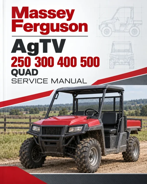
The Massey Ferguson AgTV 250, 300, 400 and 500 Quad ATV Service Manual provides technical information for maintaining, inspecting, troubleshooting and repairing the covered Massey Ferguson all-terrain vehicles. The documentation includes model-specific specifications, periodic maintenance, petrol engine and transmission repairs, carburettor and fuel systems, lubrication and cooling, electrical wiring, drive axles, suspension, steering, brakes, chassis components and operating controls.
Repair topics include engine and crankcase disassembly, clutch adjustment, carburettor servicing, oil pump pressure testing, differential and axle repairs, ignition and starter diagnostics, and steering and suspension adjustments. The contents below group repeated topics under shared technical headings, while retaining references that are genuinely configuration-specific, including 500 cc automatic transmissions and certain brake, drive and V-belt arrangements.
Notice: The original manual has separate 250/300 cc and 400/500 cc sections. Shared topic labels below are condensed for readability, not an indication that specifications or parts are interchangeable. Confirm the model, drive type and transmission before using a procedure.
Table of Contents
Massey Ferguson AgTV 250, 300, 400, 500 Manual
-
01. General Information and Model Specifications
- Engine and Transmission Specifications
- Valve and Valve Guide Specifications
- Camshaft and Cylinder Head Specifications
- Cylinder, Piston and Piston Ring Specifications
- Crankshaft Specifications
- Clutch Specifications
- Carburettor Specifications
- Electrical Specifications
- Chassis and Miscellaneous Data
- 500 cc Manual and Automatic Transmission Specifications
- Break-In Procedures
- Petrol, Engine Oil and Lubricant Recommendations
- Replacement Parts Information
- Load Capacity Rating Charts
- Preparation for Storage
- Preparation After Storage
-
02. Periodic Maintenance and Adjustments
- Periodic Maintenance Charts and Lubrication Points
- Battery and Fuse Maintenance
- Air Cleaner Removal, Cleaning and Installation
- Valve/Tappet Clearance Adjustment
- Engine Compression Testing
- Spark Plug, Muffler and Spark Arrester Inspection
- Fuel and Vent Hose Inspection
- Throttle Cable and Idle RPM Adjustment
- Engine and Transmission Maintenance
- Oil Strainer Servicing
- Front Differential and Rear Drive Lubrication
- Clutch Adjustment – Manual Transmission Configurations
- Tyre, Steering and Driveshaft Inspections
- Suspension, Shock Absorber and Bushing Inspection
- Fastener and Ignition Timing Checks
- Lighting, Switch and Gear Position Indicator Inspections
- Reverse Shift Lever Adjustment – Manual Transmission
- Frame, Weld, Rack and Electrical Connection Inspection
- Hydraulic Hand Brake Servicing
- Mechanical Foot Brake – Manual Transmission
- Hydraulic Foot Brake – Automatic Transmission
- Brake Pad Measurement, Replacement and Burnishing
- Coolant Maintenance – Liquid-Cooled Models
- V-Belt Inspection and Replacement – Automatic Transmission
-
03. Engine and Transmission Repair
- Engine and Transmission Specifications
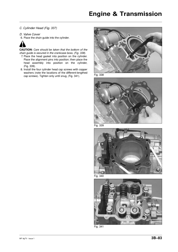
- Engine/Transmission Removal and Installation
- Top-Side Component Removal and Servicing
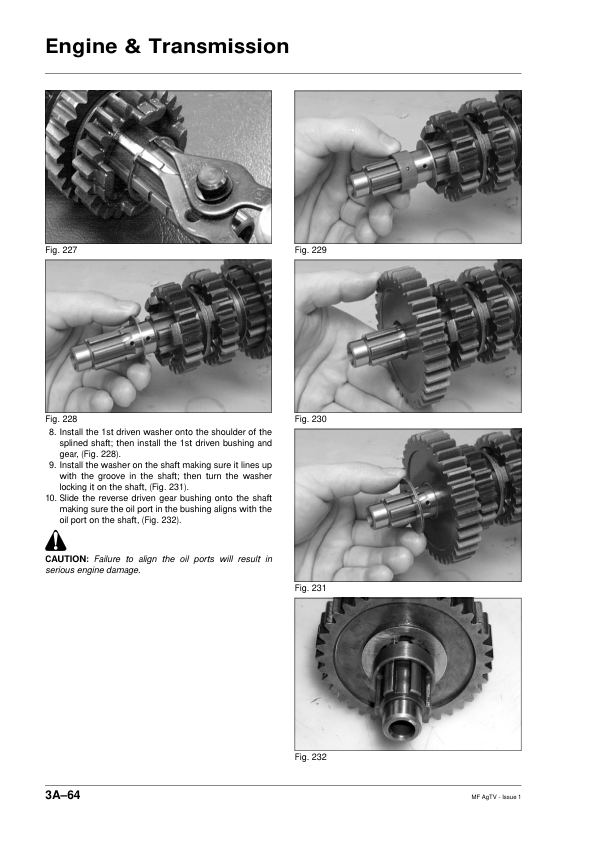
- Left-Side Component Removal and Servicing
- Right-Side Component Removal and Servicing
- Centre Crankcase Component Servicing
- Crankshaft Assembly and Overhaul
- Crankcase Half Separation and Disassembly
- Crankcase Half Inspection, Assembly and Joining
- Right-Side Component Installation
- Left-Side Component Installation
- Top-Side Component Installation
- 400 cc 2×4 Left-Side Component Installation
- 500 cc Automatic Transmission – Engine/Transmission Removal
- 500 cc Automatic Transmission – Top-, Left- and Right-Side Components
- 500 cc Automatic Transmission – Crankcase Separation and Reassembly
- 500 cc Automatic Transmission – Component Installation
- 500 cc Automatic Transmission – Centre Crankcase and Crankshaft Service
-
04. Fuel, Lubrication and Cooling Systems
- Carburettor Specifications and Schematics
- Carburettor Removal and Disassembly
- Carburettor Inspection, Cleaning and Assembly
- Carburettor Installation and Model-Specific Variations
- Throttle Cable Free Play and Engine Idle Adjustment
- Petrol Tank and Fuel Tank Valve
- Fuel and Vent Hoses
- Lubricating Oil Flow Diagrams
- Oil Pump Inspection and Pressure Testing
- Oil Cooler
- Radiator, Cooling Hoses and Thermostat
- Cooling Fan
- Liquid Cooling System and Water Pump Service
- Water Pump Service – Manual Transmission Version
-
05. Electrical System and Wiring
- Electrical Specifications and Battery
- RPM Limiter and Electrical Component Testing
- Foot and Handlebar Brake Light Switches
- Engine Oil Temperature Switch
- Cooling Fan Motor
- Accessory Receptacle and Connector
- Fuse Block and Fuses
- Gear Position Lights and Switches – Manual Transmission
- 300 cc 4×4 Gear Position Lights – Manual Transmission
- Ignition Coil, Indicator Lights and Ignition Switch
- Handlebar Control Switches and Magneto
- Starter Motor and Starter Relay
- CDI Unit and Regulator/Rectifier
- Neutral Start Relay
- Headlights and Ignition Timing
- Wiring Diagrams
-
06. Drive System, Differentials and Brakes
- Front Differential
- Differential and Rear Drive Assemblies
- Drive Axles
- Rear Axles
- Wheel Hubs
- Hydraulic Hand Brake Caliper
- Hydraulic Brake Assembly Schematics
-
07. Front and Rear Suspension
- Front and Rear Shock Absorber Assemblies
- A-Arms and Suspension Bushings
- Swing Arms – As Fitted
- Wheels and Tyres
-
08. Steering, Chassis and Frame
- Steering Post, Handlebars and Tie Rods
- Handlebar Grips and Steering Knuckles
- Toe-In and Toe-Out Measurement and Adjustment
- Body Panel Assembly Schematics
- Frame and Exhaust Assembly Schematics
- Front Rack and Bumper
- Front Fenders, Side Panels and Fender Extensions
- Belly Panel and Exhaust System
- Rear Rack, Fender and Seat
- Headlight Adjustment and Taillight Assembly
-
09. Controls and Indicators
- Hand Brake Lever and Master Cylinder Assembly
- Mechanical Foot Brake Assembly
- Hydraulic Foot Brake Assembly
- Throttle Control
- Gearshift Pedal and Drive Selector
- Reverse Shift Lever and Cable
- Shift Lever Assembly
- Speedometer, Indicators and Gear Position Lights
-
10. Torque Specifications and Conversions
- Tightening Torque Specifications
- Torque Conversion Tables
-
11. Troubleshooting
- Engine Troubleshooting
- Drive System Troubleshooting
- Fuel System Troubleshooting
- Electrical System Troubleshooting
- Steering and Suspension Troubleshooting
- Brake System Troubleshooting
Model-Specific Engine and Transmission Service References
The original workshop publication separates general information, maintenance, engine/transmission repairs, electrical service and troubleshooting into 250/300 cc and 400/500 cc model groups. This condensed index removes repeated capacity labels from common subjects; the manual retains the individual specifications and procedures for each model group.
Select the installed drivetrain before using the repair instructions. In particular, the 500 cc automatic transmission has dedicated removal and crankcase procedures, the 400 cc 2×4 model has a separate left-side component installation reference, and brake, clutch and V-belt information varies by transmission arrangement.



















Reviews
There are no reviews yet.