Overview
The Massey Ferguson 5410, 5420, 5430, 5440 and 5450 Tractor Workshop Service, Parts Catalog and Operator’s Manual collection provides technical information for maintaining, troubleshooting, repairing and operating these Massey Ferguson 5400 Series agricultural tractors. The documentation brings together workshop repair procedures, tractor specifications, component references, parts information and operating instructions for use by agricultural mechanics, service technicians and tractor owners.
Workshop service coverage includes Perkins and SisuDiesel engine configurations, GBA50 transmission systems, PowerShuttle and Powershift components, GPA50 rear axles, braking assemblies, front and rear power take-off equipment, Dana front axles, four-wheel-drive components, hydraulics, electrical equipment and cab servicing. Technical sections provide transmission adjustments, hydraulic pressure testing, component disassembly and reassembly, fault-code references, electrical diagrams and special service tool information.
Manual Collection: Workshop service manuals listed at 2,111 and 3,680 pages; Parts Catalog Manual listed at 460 pages; Operator’s Manual listed at 212 pages. Format: Digital document. Publication Numbers: 3378545M5, 4373098M2 and 4373019M2.
Important Information: The uploaded workshop bookmarks cover the wider MF 5400 Series, including additional tractor models and different Perkins, SisuDiesel, transmission, front axle and hydraulic configurations. Not every workshop procedure applies to the MF 5410, 5420, 5430, 5440 and 5450. The publication numbers and document page counts above are retained from the supplied product listing; separate parts catalog and operator’s manual indexes were not provided for verification.
Table of Contents
Massey Ferguson 5410, 5420, 5430, 5440, 5450 Workshop Service Manual
-
01. Introduction and Specifications
- 1A10 – MF 5400 Series Tractors – General Information
- Using the Workshop Manual
- General Tractor Specifications
- MF 5410 and MF 5420 Specifications
- MF 5430 Specifications
- MF 5440 Specifications
- MF 5450 Specifications
- Specifications for Additional MF 5400 Series Models
- Tractor Forward Speeds
- Dyna-4 Transmission Ground Speed References
- GTA2520 Transmission Dimensions and Attachment Points
- GTA5050 Transmission Dimensions and Attachment Points
- GTA2520 Transmission Capacities
- GTA5050 Transmission Capacities
- Hydraulic Accumulator Pressure and Volume
- Conversion Tables
- Retaining Compounds and Sealing Products
- 1A11 – MF 5400 Series Tractors – Error Codes
- Perkins Engine Error Codes
- SisuDiesel Tier 3 Engine Error Codes
- Linkage Error Codes
- Suspended Front Axle Error Codes
- GTA2520 Transmission Error Codes
- GTA5050 Transmission Error Codes
- 1A12 – Fuse Boxes, Electrical Diagrams, Harnesses and Hydraulic Diagrams
- GTA2520 Transmission Electrical Diagrams
- GTA5050 Transmission Electrical Diagrams
- PowerShuttle and Transmission Wiring Diagrams
- Four-Wheel-Drive and Differential Lock Wiring
- Front and Rear PTO Electrical Diagrams
- Perkins and SisuDiesel Engine Electrical Diagrams
- CAN Network and Electronic Injection Wiring
- Lighting, Instrument Panel and Cab Electrical Diagrams
- Open Centre and Load Sensing Hydraulic Diagrams
- 1A16 – MF 5400 Series Adjustments, Bleeding and Calibrations
- Manoeuvring Pedal Adjustment
- Rear Linkage Calibration
- Suspended Front Axle Calibration
- PowerShuttle Calibration
-
02. Separation of Assemblies
- 2A17 – Cab – Disassembly and Reassembly
- Removing and Refitting the Cab
-
03. Engine
- 3A10 – Sisu Tier 3 Engine – General Information
- Sisu Engine Technical Specifications
- Engine Mechanical Operating Principles
- Engine Lubrication System
- Engine Cooling System
- Intake and Exhaust System
- Fuel System
- Electronic Control Circuit
- 3A13 – Sisu Tier 3 Engine – Layout of Components
- Lubrication and Cooling System Components
- Fuel System Components
- Common Rail Electronic System
- 3A14 – Sisu Tier 3 Engine – Tests and Diagnostics
- Fuel Supply Pressure Measurement
- Engine Oil Pressure Measurement
- 3A16 – Sisu Tier 3 Engine – Adjustments, Bleeding and Calibrations
- Valve Clearance Adjustment
- Throttle Pedal Potentiometer Adjustment
- Fuel System Bleeding
- 3A17 – Sisu Tier 3 Engine – Disassembly and Reassembly
- Cylinder Block and Flywheel Housing
- Cylinder Head and Valve Mechanism
- Crankshaft, Connecting Rods and Pistons
- Timing Housing Assembly
- Engine Lubrication and Cooling Systems
- Intake and Exhaust Components
- Fuel Injectors and Injection Pump
- Engine Electrical Controls
- 3A18 – Sisu Tier 3 Engine – Service Tools
- 3B10 – Perkins 1104D Tier 3 Mechanical Engine
- 3B20 – Perkins 1104D Tier 3 Electronic Engine
- Perkins Engine Supplementary Service Documents
- 04. Clutch
-
05. Gearbox and Transmission Systems
- 5A10 – GBA50 Gearbox – General Information
- GBA50 Transmission Construction and Operation
- GBA50 Gearbox Kinematics
- 5A12 – GBA50 – Electrical and Hydraulic Diagrams
- 5A13 – GBA50 – Layout of Components
- Powershift Module
- PowerShuttle Module
- Robotic Mechanical Gearbox Module
- 5A16 – GBA50 – Adjustments, Bleeding and Calibrations
- Selector Rail and Fork Adjustment
- Synchroniser Overhaul
- PowerShuttle Calibration
- 5A17 – GBA50 – Disassembly and Reassembly
- 5A20 – GBA50 PowerShuttle – General Information
- 5A22 – GBA50 PowerShuttle – Electrical and Hydraulic Diagrams
- 5A23 – GBA50 PowerShuttle – Layout of Components
- 5A27 – GBA50 PowerShuttle – Disassembly and Reassembly
- PowerShuttle Module Removal
- Forward and Reverse Clutch Servicing
- Clutch Bell Housing Components
- 5A28 – GBA50 PowerShuttle – Service Tools
- 5A30 – GBA50 Powershift Module – General Information
- 5A32 – GBA50 Powershift Module – Electrical and Hydraulic Diagrams
- 5A33 – GBA50 Powershift Module – Layout of Components
- 5A37 – GBA50 Powershift Module – Disassembly and Reassembly
- Front and Rear Powershift Module Removal and Refitting
- Planet Carrier and Planet Gear Servicing
- 5A38 – GBA50 Powershift Module – Service Tools
- 5A40 – GBA50 Robotic Mechanical Gearbox – General Information
- Robotic Gearbox Operating Principles and Range Selection
- 5A42 – Robotic Mechanical Gearbox – Electrical and Hydraulic Diagrams
- 5A43 – Robotic Mechanical Gearbox – Layout of Components
- 5A47 – Robotic Mechanical Gearbox – Disassembly and Reassembly
- Primary and Secondary Shaft Servicing
- Selector Rail Assembly Overhaul
- Gearbox Shaft Shimming
- 5A48 – Robotic Mechanical Gearbox – Service Tools
- 5A60 – GBA50 Super Creeper Gears – General Information
- 5A63 – Super Creeper Gears – Layout of Components
- 5A66 – Super Creeper Gears – Adjustments and Calibrations
- 5A67 – Super Creeper Gears – Disassembly and Reassembly
- 5A68 – Super Creeper Gears – Service Tools
-
06. Rear Axle, Differential and Braking System
- 6A10 – GPA50 Rear Axle – General Information
- GPA50 Rear Axle Operating Principles
- Two-Speed and Three-Speed PTO Kinematics
- Super Creeper Gear Mechanism
- 6A12 – GPA50 – Electrical and Hydraulic Diagrams
- 6A13 – GPA50 – Layout of Components
- Centre Housing and Rear Axle Assemblies
- 6A17 – GPA50 – Disassembly and Reassembly
- 6A20 – GPA50 Trumpet Housings – General Information
- GPA51, GPA52 and GPA54 Trumpet Housings
- 6A22 – Trumpet Housings – Electrical and Hydraulic Diagrams
- 6A23 – Trumpet Housings – Layout of Components
- 6A26 – Trumpet Housings – Adjustments and Calibrations
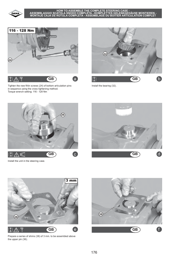
- Planet Gear and Axle Bearing Shimming
- 6A27 – Trumpet Housings – Disassembly and Reassembly
- Trumpet Housing and Planet Carrier Overhaul
- Axle Bearing and Oil Seal Replacement
- 6A28 – Trumpet Housings – Service Tools
- 6A30 – GPA50 Rear Crownwheel and Pinion – General Information
- Rear Crownwheel and Pinion 9×40 and 10×42
- 6A32 – Rear Crownwheel and Pinion – Electrical and Hydraulic Diagrams
- 6A33 – Rear Crownwheel and Pinion – Layout of Components
- 6A36 – Rear Crownwheel and Pinion – Adjustments and Calibrations
- Pinion Position and Bearing Shimming
- Differential Ring Gear Backlash Adjustment
- 6A37 – Rear Crownwheel and Pinion – Disassembly and Reassembly
- Rear Differential and Differential Lock Servicing
- Ring Gear, Planet Gear and Pinion Overhaul
- 6A38 – Rear Crownwheel and Pinion – Service Tools
- 6A40 – GPA50 Tractor Braking – General Information
- 6A42 – Tractor Braking – Electrical and Hydraulic Diagrams
- 6A43 – Tractor Braking – Layout of Components
- 6A46 – Tractor Braking – Adjustments, Bleeding and Calibrations
- Main Brake and Parking Brake Adjustment
- Main Brake System Bleeding
- 6A47 – Tractor Braking – Disassembly and Reassembly
- Brake Disc, Intermediate Plate and Hydraulic Brake Unit Servicing
- 6A48 – Tractor Braking – Service Tools
- 6A50 – GPA50 Hydraulic Trailer Braking – General Information
- 6A52 – Hydraulic Trailer Braking – Electrical and Hydraulic Diagrams
- 6A53 – Hydraulic Trailer Braking – Layout of Components
- 6A56 – Hydraulic Trailer Braking – Adjustments and Bleeding
- 6A58 – Hydraulic Trailer Braking – Service Tools
-
07. Power Take-Off (PTO)
- 7A10 – GPA50 Two-Speed Electrohydraulic Rear PTO – General
- 7A12 – Two-Speed Rear PTO – Electrical and Hydraulic Diagrams
- 7A13 – Two-Speed Rear PTO – Layout of Components
- 7A16 – Two-Speed Rear PTO – Adjustments and Calibrations
- Two-Speed PTO Shaft Shimming
- 7A17 – Two-Speed Rear PTO – Disassembly and Reassembly
- 7A18 – Two-Speed Rear PTO – Service Tools
- 7A20 – GPA50 Three-Speed Electrohydraulic Rear PTO – General
- 7A22 – Three-Speed Rear PTO – Electrical and Hydraulic Diagrams
- 7A23 – Three-Speed Rear PTO – Layout of Components
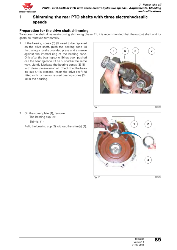
- 7A26 – Three-Speed Rear PTO – Adjustments and Calibrations
- Three-Speed PTO Shaft Shimming
- 7A27 – Three-Speed Rear PTO – Disassembly and Reassembly
- 7A28 – Three-Speed Rear PTO – Service Tools
- 7A30 – GPA50 Rear PTO Clutch – General Information
- 7A32 – Rear PTO Clutch – Electrical and Hydraulic Diagrams
- 7A33 – Rear PTO Clutch – Layout of Components
- Gerotor Lubrication Pump and PTO Clutch Assembly
- 7A37 – Rear PTO Clutch – Disassembly and Reassembly
- Rear PTO Clutch and Gerotor Pump Overhaul
- 7A38 – Rear PTO Clutch – Service Tools
- 7C10 – Zuidberg Front Power Take-Off – General Information
- 7C12 – Zuidberg Front PTO – Electrical and Hydraulic Diagrams
- 7C13 – Zuidberg Front PTO – Layout of Components
- 7C14 – Zuidberg Front PTO – Tests and Diagnostics
- Front PTO Hydraulic and Electrical Tests
- 7C16 – Zuidberg Front PTO – Adjustments and Maintenance
- Front PTO Oil Draining and Filter Replacement
- 7C17 – Zuidberg Front PTO – Disassembly and Reassembly
-
08. Front Axle, Four-Wheel Drive and Steering
- 8A10 – DANA 720 Front Axle – General Information
- 8A12 – DANA 720 – Electrical and Hydraulic Diagrams
- 8A13 – DANA 720 – Layout of Components
- 8A14 – DANA 720 – Tests and Diagnostics
- 8A17 – DANA 720 – Disassembly and Reassembly
- 8B10 – DANA 725 Front Axle – General Information
- 8B12 – DANA 725 – Electrical and Hydraulic Diagrams
- 8B13 – DANA 725 – Layout of Components
- 8B14 – DANA 725 – Tests and Diagnostics
- 8B17 – DANA 725 – Disassembly and Reassembly
- 8C10 – DANA 730 Fixed Front Axle – General Information
- 8C12 – DANA 730 Fixed Axle – Electrical and Hydraulic Diagrams
- 8C13 – DANA 730 Fixed Axle – Layout of Components
- 8C14 – DANA 730 Fixed Axle – Tests and Diagnostics
- 8C17 – DANA 730 Fixed Axle – Disassembly and Reassembly
- 8C20 – DANA 730 Suspended Front Axle – General Information
- 8C22 – DANA 730 Suspended Axle – Electrical and Hydraulic Diagrams
- 8C23 – DANA 730 Suspended Axle – Layout of Components
- 8C24 – DANA 730 Suspended Axle – Tests and Diagnostics
- 8C27 – DANA 730 Suspended Axle – Disassembly and Reassembly
- 8D10 – DANA 735 Fixed Front Axle – General Information
- 8D12 – DANA 735 Fixed Axle – Electrical and Hydraulic Diagrams
- 8D13 – DANA 735 Fixed Axle – Layout of Components
- 8D14 – DANA 735 Fixed Axle – Tests and Diagnostics
- 8D17 – DANA 735 Fixed Axle – Disassembly and Reassembly
- 8D20 – DANA 735 Suspended Front Axle – General Information
- 8D22 – DANA 735 Suspended Axle – Electrical and Hydraulic Diagrams
- 8D23 – DANA 735 Suspended Axle – Layout of Components
- 8D24 – DANA 735 Suspended Axle – Tests and Diagnostics
- 8D27 – DANA 735 Suspended Axle – Disassembly and Reassembly
- 8G10 – GPA50 Four-Wheel-Drive Clutch – General Information
- 8G12 – Four-Wheel-Drive Clutch – Electrical and Hydraulic Diagrams
- 8G13 – Four-Wheel-Drive Clutch – Layout of Components
- 8G16 – Four-Wheel-Drive Clutch – Adjustments and Calibrations
- 8G17 – Four-Wheel-Drive Clutch – Disassembly and Reassembly
- 8G18 – Four-Wheel-Drive Clutch – Service Tools
- 8I10 – Open Centre Steering Unit – General Information
- DANA Axle Supplementary Service Documents
-
09. Hydraulic Systems
- 9A10 – GTA5050 Open Centre Hydraulics – General Information
- 57 L/min Open Centre Hydraulic System
- 9A12 – GTA5050 Open Centre – Electrical and Hydraulic Diagrams
- 9A13 – GTA5050 Open Centre – Layout of Components
- 9A14 – GTA5050 Open Centre – Tests and Diagnostics
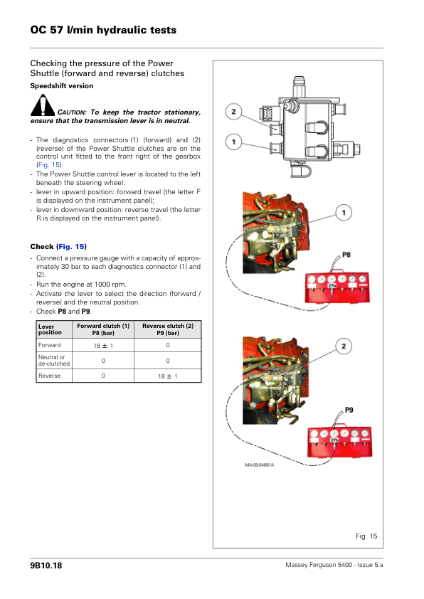
- High-Flow and Low-Flow Hydraulic Testing
- 9A20 – GTA5050 Open Centre Right-Hand Cover Plate – General
- 9A22 – Right-Hand Cover Plate – Electrical and Hydraulic Diagrams
- 9A23 – Right-Hand Cover Plate – Layout of Components
- 9A27 – Right-Hand Cover Plate – Disassembly and Reassembly
- High-Pressure and 21-Bar Valve Servicing
- Lubrication and Thermostatic Valve Servicing
- 9B10 – GTA5050 100 L/min Open Centre – General Information
- 9B12 – GTA5050 100 L/min Open Centre – Electrical and Hydraulic Diagrams
- 9B13 – GTA5050 100 L/min Open Centre – Layout of Components
- 9B14 – GTA5050 100 L/min Open Centre – Tests and Diagnostics
- 9B20 – 100 L/min Open Centre Right-Hand Cover Plate – General
- 9B22 – Right-Hand Cover Plate – Electrical and Hydraulic Diagrams
- 9B23 – Right-Hand Cover Plate – Layout of Components
- 9B27 – Right-Hand Cover Plate – Disassembly and Reassembly
- 9B30 – 100 L/min Open Centre Left-Hand Cover Plate – General
- 9B32 – Left-Hand Cover Plate – Electrical and Hydraulic Diagrams
- 9B33 – Left-Hand Cover Plate – Layout of Components
- 9B37 – Left-Hand Cover Plate – Disassembly and Reassembly
- 9C10 – GTA5050 Open Centre Spool Valves – General Information
- 9C12 – Spool Valves – Electrical and Hydraulic Diagrams
- 9C13 – Spool Valves – Layout of Components
- 9C17 – Spool Valves – Disassembly and Reassembly
- 9C20 – GTA5050 Open Centre Rear Linkage – General Information
- 9C22 – Rear Linkage – Electrical and Hydraulic Diagrams
- 9C23 – Rear Linkage – Layout of Components
- 9C24 – Rear Linkage – Tests and Diagnostics
- 9C27 – Rear Linkage – Disassembly and Reassembly
- 9C30 – GTA5050 Open Centre Front Linkage – General Information
- 9C32 – Front Linkage – Electrical and Hydraulic Diagrams
- 9C36 – Front Linkage – Adjustments and Calibrations
- 9D10 – GPA50 Brake Master Cylinders – General Information
- 9D12 – Brake Master Cylinders – Electrical and Hydraulic Diagrams
- 9D13 – Brake Master Cylinders – Layout of Components
- 9D16 – Brake Master Cylinders – Adjustments and Bleeding
- 9D17 – Brake Master Cylinders – Service and Maintenance
- 9D18 – Brake Master Cylinders – Service Tools
- 9D20 – GPA50 Hydraulic Trailer Braking – General Information
- 9D22 – Hydraulic Trailer Braking – Electrical and Hydraulic Diagrams
- 9D23 – Hydraulic Trailer Braking – Layout of Components
- 9D26 – Hydraulic Trailer Braking – Adjustments and Bleeding
- 9D28 – Hydraulic Trailer Braking – Service Tools
-
10. Electrical Equipment
- 10A12 – Lighting and Equipment – Electrical Diagrams
- 10A13 – Lighting and Equipment – Layout of Components
- 10B10 – Fuse Box – General Information
- 10B12 – Fuse Box – Electrical and Hydraulic Diagrams
- 10B13 – Fuse Box – Layout of Components
- 10C14 – Alternator – Tests and Diagnostics
- Alternator Testing and Component Inspection
- 10E10 – Starter Motor – General Information
- 10E14 – Starter Motor – Tests and Diagnostics
- 11. Electronics
-
12. Cab and Equipment
- 12A10 – Standard Air Conditioning – General Information
- 12A12 – Standard Air Conditioning – Electrical and Hydraulic Diagrams
- 12A14 – Standard Air Conditioning – Tests and Diagnostics
- 12A16 – Standard Air Conditioning – Adjustments and Maintenance
- Air-Conditioning Compressor Servicing
- 12B10 – Cab Suspension – General Information
- 12B12 – Cab Suspension – Electrical and Hydraulic Diagrams
- 12B13 – Cab Suspension – Layout of Components
- 12B17 – Cab Suspension – Disassembly and Reassembly
- Mechanical Cab Suspension and Support Servicing
- 13. Accessories
-
14. Service Tools
- 14A01 – General
- 14A03 – Engine
- Sisu Tier 3 Engine Service Tools
GBA50 Gearbox, GPA50 Rear Axle and Power Take-Off Service
The MF 5400 Series workshop documentation provides technical references for engine servicing, GBA50 transmission repairs, GPA50 rear axle maintenance, PTO assemblies, front axles and hydraulic systems. The supplied product description also explains warranty failure-code recording: for example, a six-digit failure code of 43 04 03 combined with fault code 14 is recorded as 43 04 03 14. Consult the applicable repair-time schedule and current warranty requirements when using these references.




























Reviews
There are no reviews yet.