Massey Ferguson 7485, 7490, 7495, 7497, 7499 Tractor Workshop Service Manual

$45.00

What’s Included

Workshop Service Manual 1392 Pages (Up to year 2008)
Workshop Service Manual 2872 Pages (From year 2009)
Technician Repair Manual 282 Pages
Operating Manual 232 Pages (Dyna VT Tier 2)
Operating Manual 276 Pages (Dyna Tier 3)
Repair Time Schedule 697 Pages (Tier 2)

Technical Details

Brand Massey Ferguson
Models Covered 7485, 7490, 7495, 7497, 7499
Machine Type Tractor
Documentation Workshop Manual, Service Repair Manual, Operating Manual, Repair Time Schedule
Publication Numbers 7060389M1 & 4346420M1 & 337855M7
Language English
Format PDF
SKU: 854663 Category:
Guaranteed Safe Checkout

Overview

The Massey Ferguson 7485, 7490, 7495, 7497 and 7499 Tractor Workshop Service Repair Manual provides technical information for maintaining, diagnosing and repairing these Massey Ferguson 7400 Series agricultural tractors. The documentation includes tractor specifications, component identification, mechanical repair procedures, electrical and hydraulic diagrams, fault codes, system calibrations and servicing instructions for major tractor assemblies.

Coverage includes the Dyna-VT continuously variable transmission (CVT), ML130 and ML160 transmission systems, HA130/160 rear axle assemblies, final drives, differential components, tractor and trailer braking, ParkLock, four-wheel-drive systems and suspended Dana front axles. The manual also identifies engine, clutch, power take-off, hydraulic, electrical, electronic, cab and accessory sections for workshop reference.

The detailed electronic documentation addresses DCC2 instrument displays, Datatronic 3, ISOBUS, Auto-Guide, CAN network connections, controller programming, electrical diagnostics and system calibration. Separate workshop procedures cover Dyna-VT transmission removal and reassembly, differential servicing, brake adjustment, suspended front axle calibration and electronic component testing.

Safety: Review the applicable workshop instructions before servicing high-pressure hydraulic circuits, transmission assemblies, braking equipment or suspended axle systems. Depressurise hydraulic circuits and support tractor assemblies according to the relevant service procedures before component removal.

Notice: The MF 7400 Series documentation also contains specifications for the 7465, 7475 and 7480 models, alongside the 7485, 7490, 7495, 7497 and 7499. Some procedures relate to alternative Perkins and Sisu engines, transmission arrangements, axle types and optional electronic equipment. Verify the tractor model, serial number and fitted components before selecting a repair procedure.

Table of Contents

Massey Ferguson 7485, 7490, 7495, 7497, 7499 Manual

  • 01. Introduction
    • 1A10 – 7400 Series Tractors – General
    • 1A11 – 7400 Series Tractors – Error Codes
    • 1A12 – 7400 Series Tractors – Electrical and Hydraulic Diagrams
    • 1A16 – 7400 Series Tractors – Adjustments, Bleeding and Calibrations
  • 02. Separation of Assemblies
  • 03. Engine
  • 04. Clutch
  • 05. Gearbox
    • 5A10 – ML130 / ML160 – General
    • 5A11 – ML130 / ML160 – Error Codes
    • 5A12 – ML130 / ML160 – Electrical and Hydraulic Diagrams
    • 5A14 – ML130 / ML160 – Tests and Diagnostics
    • 5A15 – ML130 / ML160 – Programming and Setting Parameters
    • 5A16 – ML130 / ML160 – Adjustments, Bleeding and Calibrations
    • 5A17 – ML130 / ML160 – Disassembly and Reassembly
    • 5A18 – ML130 / ML160 – Service Tools
  • 06. Rear Axle
    • 6A11 – HA130/160 – Error Codes
    • 6A15 – HA130/160 – Programming and Setting Parameters
    • 6A16 – HA130/160 – Adjustments, Bleeding and Calibrations
    • 6A23 – HA130/160 / Final Drives – Layout of Components
    • 6A25 – HA130/160 / Final Drives – Programming and Setting Parameters
    • 6A27 – HA130/160 / Final Drives – Disassembly and Reassembly
    • 6A31 – HA130/160 / Differential – Error Codes
    • 6A32 – HA130/160 / Differential – Electrical and Hydraulic Diagrams
    • 6A33 – HA130/160 / Differential – Layout of Components
    • 6A34 – HA130/160 / Differential – Tests and Diagnostics
    • 6A35 – HA130/160 / Differential – Programming and Setting Parameters
    • 6A36 – HA130/160 / Differential – Adjustments, Bleeding and Calibrations
    • 6A37 – HA130/160 / Differential – Disassembly and Reassembly
    • 6A41 – HA130/160 / Tractor Braking – Error Codes
    • 6A42 – HA130/160 / Tractor Braking – Electrical and Hydraulic Diagrams
    • 6A43 – HA130/160 / Tractor Braking – Layout of Components
    • 6A47 – HA130/160 / Tractor Braking – Disassembly and Reassembly
    • 6A50 – HA130/160 / ParkLock – General
    • 6A51 – HA130/160 / ParkLock – Error Codes
    • 6A52 – HA130/160 / ParkLock – Electrical and Hydraulic Diagrams
    • 6A53 – HA130/160 / ParkLock – Layout of Components
    • 6A54 – HA130/160 / ParkLock – Tests and Diagnostics
    • 6A55 – HA130/160 / ParkLock – Programming and Setting Parameters
    • 6A56 – HA130/160 / ParkLock – Adjustments, Bleeding and Calibrations
    • 6A61 – HA130/160 / Hydraulic Trailer Braking – Error Codes
    • 6A62 – HA130/160 / Hydraulic Trailer Braking – Electrical and Hydraulic Diagrams
    • 6A64 – HA130/160 / Hydraulic Trailer Braking – Tests and Diagnostics
    • 6A65 – HA130/160 / Hydraulic Trailer Braking – Programming and Setting Parameters
    • 6A70 – HA130/160 / Pneumatic Trailer Braking – General
    • 6A72 – HA130/160 / Pneumatic Trailer Braking – Electrical and Hydraulic Diagrams
    • 6A73 – HA130/160 / Pneumatic Trailer Braking – Layout of Components
    • 6A74 – HA130/160 / Pneumatic Trailer Braking – Tests and Diagnostics
    • 6A76 – HA130/160 / Pneumatic Trailer Braking – Adjustments, Bleeding and Calibrations
    • 6A82 – HA130/160 / Auto-Hitch – Electrical and Hydraulic Diagrams
  • 07. Power Take-Off
  • 08. Front Axle
    • 8A11 – Dana 735 – Error Codes
    • 8A12 – Dana 735 – Electrical and Hydraulic Diagrams
    • 8A14 – Dana 735 – Tests and Diagnostics
    • 8A15 – Dana 735 – Programming and Setting Parameters
    • 8A16 – Dana 735 – Adjustments, Bleeding and Calibrations
    • 8A17 – Dana 735 – Disassembly and Reassembly
    • 8B11 – Dana 740 – Error Codes
    • 8B12 – Dana 740 – Electrical and Hydraulic Diagrams
    • 8B14 – Dana 740 – Tests and Diagnostics
    • 8B15 – Dana 740 – Programming and Setting Parameters
    • 8B16 – Dana 740 – Adjustments, Bleeding and Calibrations
    • 8B17 – Dana 740 – Disassembly and Reassembly
    • 8C11 – Dana 745 – Error Codes
    • 8C12 – Dana 745 – Electrical and Hydraulic Diagrams
    • 8C14 – Dana 745 – Tests and Diagnostics
    • 8C15 – Dana 745 – Programming and Setting Parameters
    • 8C16 – Dana 745 – Adjustments, Bleeding and Calibrations
    • 8C17 – Dana 745 – Disassembly and Reassembly
    • 8D11 – Dana 750 – Error Codes
    • 8D12 – Dana 750 – Electrical and Hydraulic Diagrams
    • 8D14 – Dana 750 – Tests and Diagnostics
    • 8D15 – Dana 750 – Programming and Setting Parameters
    • 8D16 – Dana 750 – Adjustments, Bleeding and Calibrations
    • 8D17 – Dana 750 – Disassembly and Reassembly
    • 8E11 – Dana 755 – Error Codes
    • 8E12 – Dana 755 – Electrical and Hydraulic Diagrams
    • 8E14 – Dana 755 – Tests and Diagnostics
    • 8E15 – Dana 755 – Programming and Setting Parameters
    • 8E16 – Dana 755 – Adjustments, Bleeding and Calibrations
    • 8E17 – Dana 755 – Disassembly and Reassembly
    • 8G11 – 4WD Clutch – Error Codes
    • 8G12 – 4WD Clutch – Electrical and Hydraulic Diagrams
    • 8G14 – 4WD Clutch – Tests and Diagnostics
    • 8G15 – 4WD Clutch – Programming and Setting Parameters
    • 8G16 – 4WD Clutch – Adjustments, Bleeding and Calibrations
  • 09. Hydraulics
  • 10. Electricity
  • 11. Electronics
    • 11A10 – DCC2 – General
    • 11A11 – DCC2 – Error Codes
    • 11A12 – DCC2 – Electrical and Hydraulic Diagrams
    • 11A15 – DCC2 – Programming and Setting Parameters
    • 11B10 – Datatronic 3 – General
    • 11B12 – Datatronic 3 – Electrical and Hydraulic Diagrams
    • 11B15 – Datatronic 3 – Programming and Setting Parameters
    • Datatronic 3 – Adjustments, Bleeding and Calibrations
    • 11C12 – ISOBUS – Electrical and Hydraulic Diagrams
    • 11D12 – Auto-Guide – Electrical and Hydraulic Diagrams
    • 11D14 – Auto-Guide – Tests and Diagnostics
    • 11D15 – Auto-Guide – Programming and Setting Parameters
    • 11D16 – Auto-Guide – Adjustments, Bleeding and Calibrations
    • 11D17 – Auto-Guide – Disassembly and Reassembly
    • 11D18 – Auto-Guide – Service Tools
  • 12. Cab and Equipment
  • 13. Accessories
  • 14. Service Tools

Dyna-VT Transmission Maintenance and Diagnostic Procedures

The gearbox documentation covers ML130 and ML160 continuously variable transmission systems, including Dyna-VT operating principles, Dyna-TM traction control references, electronic error codes and electrical and hydraulic circuit diagrams. The diagnostic sections include hydrostatic loop inspection, hydraulic pressure measurement, safety-function testing and gearbox electrical testing.

Further procedures describe controller programming, parameter settings, forward speed calibration, throttle pedal potentiometer adjustment, armrest lever calibration and Autotronic 4 functions. The repair sections include disassembly and reassembly of the Dyna-VT unit, transmission filling, forward/reverse high-pressure relief valves and flushing valve servicing.

Rear Axle, Differential and Braking System Servicing

The HA130/160 rear axle documentation includes final drive assemblies, differential components, electrical control diagrams and mechanical repair procedures. Detailed topics cover removal and refitting of final drive units, differential and pinion disassembly, electronic diagnostic tests, programming and system calibration.

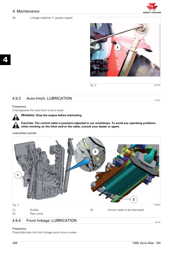
Tractor braking references include hydraulic brake components, wheel brake cylinders, brake bleeding and ParkLock. Separate sections cover hydraulic trailer braking, pneumatic trailer braking and the Auto-Hitch system. The pneumatic trailer braking material distinguishes German, English and Italian system arrangements, allowing the appropriate component and testing references to be selected.

Dana Suspended Front Axles and Four-Wheel-Drive System

The front axle documentation provides dedicated technical sections for Dana 735, 740, 745, 750 and 755 axle arrangements. Each axle group includes electrical and hydraulic diagrams, fault codes, diagnostic testing, programming, calibration and disassembly or reassembly references. Additional documentation addresses the four-wheel-drive clutch, including electrical controls, system testing and adjustment procedures.

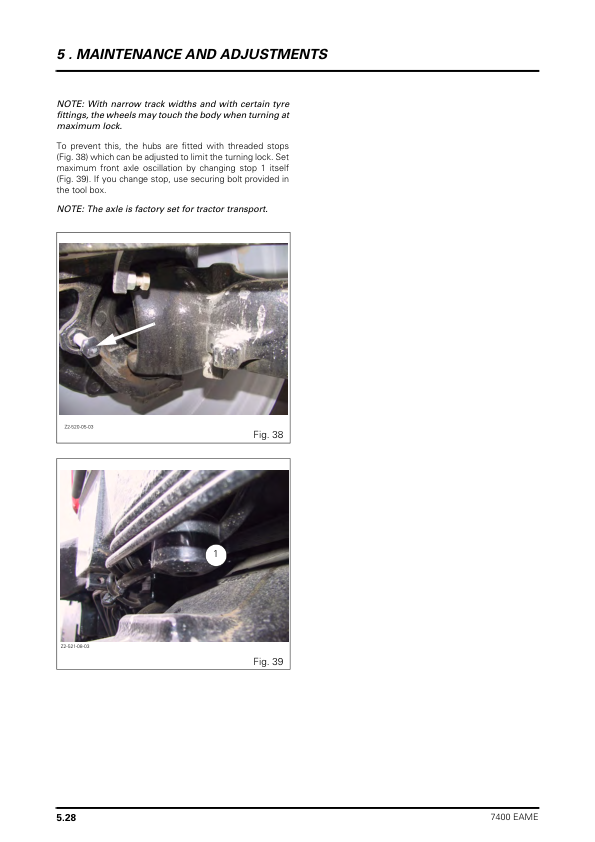
Identify the axle fitted to the tractor before carrying out suspended front axle calibration, electrical diagnosis or component removal. The applicable axle and control system procedures should be used when inspecting the suspension or four-wheel-drive equipment.

Electronic Control Systems, Datatronic 3 and Auto-Guide

The electronics chapter provides technical information for the DCC2 instrument display, Datatronic 3, ISOBUS and Auto-Guide systems. It includes controller electrical connections, CAN network diagrams, instrument panel error codes, system parameter settings and programming instructions.

Auto-Guide references include diagnostic testing, steering unit valve programming, TopDock configuration, authorisation code procedures, radio parameter settings, DMU calibration and Auto-Guide harness installation. Additional diagrams distinguish Datatronic 3 and non-Datatronic 3 tractor configurations, as well as joystick and FingerTIP control arrangements.

Model Identification and Workshop Specifications

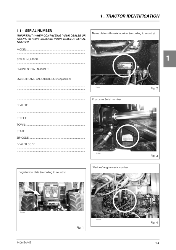
The introductory documentation includes tractor specifications for the Massey Ferguson 7485, 7490, 7495, 7497 and 7499, along with dimensions, weights, attachment points and capacities. It also includes additional 7400 Series model information, conversion tables, retaining compounds, sealing products, electrical diagrams, hydraulic diagrams, fault codes and calibration procedures.

Before servicing the tractor, verify the model, engine and transmission configuration and confirm whether the relevant axle, braking or electronic equipment is installed. This helps ensure that the correct technical references are selected for component inspection, diagnosis and repair.


Reviews

There are no reviews yet.

Only logged in customers who have purchased this product may leave a review.

Massey Ferguson 7485, 7490, 7495, 7497, 7499 Tractor Service Manual
Massey Ferguson 7485, 7490, 7495, 7497, 7499 Tractor Workshop Service Manual

$45.00

Add to cart