Overview
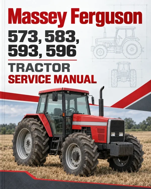
The Massey Ferguson 573, 583, 593 and 596 Tractor Workshop Service Manual provides technical information for the maintenance, diagnosis and repair of these MF 500 Series tractors. It covers workshop servicing procedures, component inspection, mechanical adjustments, technical specifications and the repair of major tractor assemblies.
Coverage includes Perkins 1100 Series Tier II diesel engines, Carraro two-wheel-drive and four-wheel-drive axles, dual-stage and split-torque clutches, 8×2, 8×8 and 12×4 gearboxes, rear axle assemblies, Ferguson hydraulic linkage, independent power take-off and auxiliary hydraulics. Further sections address tractor separation, electrical equipment, cab heating and air conditioning, troubleshooting and workshop tools.
Safety: The introductory material includes workshop safety practices and recommended servicing techniques. Dedicated air conditioning chapters also provide safety precautions for refrigerant handling. Consult the relevant instructions before carrying out mechanical repairs or system servicing.
Table of Contents
Massey Ferguson 573, 583, 593, 596 Manual
-
A. Introduction
- 1. Presentation
- 2. Safety
- 3. Correct Workshop Techniques
- 4. Basics of Measurement
- 5. General Table of Recommended Torques for Bolts
- 6. Technical Units
- 7. Products for the Workshop
- 8. AGCO Environmental Policy
- 9. Compulsory Recycling of Batteries
-
B. Splitting the Tractor
- 1. Introduction
- 2. Splitting the Tractor Between the Engine and Front Axle
- 3. Splitting the Tractor Between the Engine and Gearbox
- 4. Splitting the Tractor Between the Gearbox and Rear Axle
- 5. ROPS, Canopy and Fender Assembly Removal
- 6. Front Hood Sheet Metal Removal
- 7. Cab Version Tractors
-
C. Two-Wheel-Drive Front Axle
- 1. Introduction
- 2. Wheel Alignment
- 3. Front Wheel Hubs
- 4. Outer Arm and Spindle Shaft
- 5. Front Axle Central Beam
-
D. Four-Wheel-Drive Carraro Front Axles – 20.14 SD and 20.18 CD
- 1. Introduction
- 2. Final Drives
- 3. Final Drive Pivoting
- 4. Half-Shaft Universal Joints
- 5. Bushings and Retainers of Trumpets and Pivots
- 6. Pinion and Differential Assembly
- 7. Side Drive Box (20.14 Axle)
- 8. Axle 20.18 Center Drive System
- 9. Steering Cylinder
- 10. Tightening Torques
-
E. 1100 Series – Tier II Four-Cylinder Perkins Engines
- 1. Basic Technical Specifications
- 2. Adjustment of Valve Tip Clearance
- 3. Atomisers Inspection
- 4. Engine Timing
- 5. Compression Test for Cylinders
- 6. Workshop Specifications
- 7. Specific Torque Tensions
- Engine Workshop Manual (05B)
-
F. Clutches
- 1. Clutches and Flywheels Fitted on the MF 500 Series
- 2. General Information and Recommendations on Clutches
- 3. Dual-Stage and Split-Torque Clutch – Component Identification
- 4. Clutch Removal and Disassembly
- 5. Inspection and Refitting of Components
- 6. Clutch Reassembly (Dual-Stage and Split-Torque)
- 7. Engine Flywheel
- 8. Clutch Refitting and Final Adjustments
- 9. Clutch Troubleshooting
-
G1. 8×2-Speed Gearbox
- 1. Introduction
- 2. Lever Cover and Gear Shift Levers
- 3. Selector Rails and Forks
- 4. Epicyclic Unit
- 5. Clutch System
- 6. Brake Pedal Cross-Shaft
- 7. Gearbox Internal Assembly Disassembly
- 8. Gearbox Reassembly and Servicing
-
G2. 8×8 Synchro Shuttle Gearbox
- 1. Introduction
- 2. Gearbox Removal and Refitting
- 3. Clutch System
- 4. Control Levers and Tie Rods
- 5. Gearbox Top Cover
- 6. Selector Forks and Guides
- 7. Epicyclic Unit
- 8. PTO Drive Shaft Front Bearing
- 9. Front Flange and Input Shafts
- 10. PTO Output Shaft, Main Shaft, Lower Shaft and Gears
-
G3. 12×4 Synchro Gearbox
- 1. Introduction
- 2. Gearbox Removal and Adaptation to Service Support
- 3. Speed Selector System – Footstep Type Tractors
- 4. Gear Selector System – Cab Version Tractors
- 5. High/Low Range Assembly
- 6. Front Flange (Input Housing) and Input Shafts
- 7. Main Shaft (Output Shaft)
- 8. PTO Output Shaft and Layshaft
- 9. Reverse Gear Assembly
- 10. Synchronizer Assemblies
- 11. Component Inspection and Failure Diagnosis
-
H. Rear Axle
- 1. Description and Operation
- 2. Final Drives
- 3. Trumpets
- 4. Brakes
- 5. Differential
- 6. Pinion
- 7. Adjustments and Reinstallation of the Crown Gear and Pinion Assembly
- 8. General Technical Specifications
-
I. Ferguson Hydraulic Linkage System
- 1. Introduction
- 2. Ferguson Hydraulic System Operation
- 3. Ferguson Hydraulic Pump
- 4. Hydraulic Lift Cover
- 5. System Final Assembly
-
J. Independent Power Take-Off – IPTO
- 1. Introduction
- 2. Removing the IPTO Assembly
- 3. IPTO Side Cover and Control Valves Assembly
- 4. Clutch Disc Pack Assembly
- 5. Dual Rotation PTO/IPTO – 1000/540 RPM
- 6. Reinstalling the IPTO Assembly into the Tractor
- 7. Power Take-Off – PTO
- L. Electrical System
-
M. Auxiliary Hydraulic Systems
- 1. Introduction
- 2. Hydraulic Testing
- 3. Danfoss Hydrostatic Unit
- 4. Auxiliary Hydraulic Control Valve
- 5. Hydraulic Pumps
- 6. Oil Filtering
-
N. Cab, Air Conditioning and Heating
- 1. Introduction
- 2. Component Description
- 3. Safety Precautions
- 4. General Maintenance
- 5. Preventive Maintenance Control
- 6. Electrical Diagram
- 7. Refrigerant Refilling
- 8. Service Tools
- 9. Troubleshooting
- 10. Cab and Air Conditioning System Electrical Circuit
- 11. Cab External Roof and Air Conditioner Assembly
- 12. Cab Internal Roof
- 13. Control Panel
- 14. Windshield Wiper and Washer
- O. Special Tools
Engine Configurations and Clutch Troubleshooting
The engine timing documentation distinguishes the Bosch injection pump used in the MF 573 and 583 references from the Delphi injection pump identified for the MF 593 and 596. The gearbox chapters also provide separate procedures for 8×2, 8×8 Synchro Shuttle and 12×4 Synchro configurations. Select the information corresponding to the installed engine and transmission before applying adjustment or overhaul procedures.
The clutch chapter includes fault diagnosis for dual-stage and split-torque assemblies. The following troubleshooting reference reproduces four cases from the supplied technical material. Consult the complete manual for the associated inspection conditions and repair procedures.
Clutch Troubleshooting Reference
| Failure |
Possible Causes |
Solution |
| Friction plate binding |
Distortion during transportation. |
Adjust the binding. The source specifies that the friction plate should not exceed 1.00 mm. |
| Friction plate seized to pilot shaft |
- Shaft splines distorted during refitting
- Worn hub or splines
- Rust between the hub and pilot shaft
|
- Remove burrs or replace the friction plate
- Replace the friction plate, shaft or both as required
- Clean the affected components and lubricate lightly
|
| Friction plate stuck to flywheel or pressure plate |
Tractor stored for an extended period without releasing the clutch. |
Clean the flywheel, pressure plate and friction plate contact surfaces using fine sandpaper, as described in the source. |
| Friction plate seized to flywheel or pressure plate by vacuum |
Rivets without holes or dust obstructing the holes. |
- The source specifies clearing or making the hole using a 2 mm diameter drill
- Lightly abrade the clutch-facing surface with sandpaper
|


















Reviews
There are no reviews yet.